|
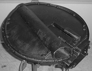
Underside Of The Burner Casting The underside of the burner is covered with a metal cover. The metal cover had been replaced sometime in the past with a stainless steel one and held in place with brass screws. While it was fairly easy to remove the cover due to the use of the brass screws, the tapped holes had to be drilled to the next screw size larger and tapped. A blanket of insulation is held in place by the cover to protect the casting from direct exposure to water splashing up from the wheels. The pilot access opening is located at the lower right corner of the photograph. In the photo is a conical tube running from the five o’clock to the eleven o’clock position. This tube is the mixing tube. The fuel nozzle is positioned at the open end of this tube to inject vaporized kerosene fuel down the central axis of the mixing tube. Combustion air is drawn in the mixing tube by the burning of the fuel above the grate and thus as the air is drawn in it mixes with the vaporized fuel in the proper ratio for combustion. At the small end of the conical tube the air and fuel mixture is admitted to the large cavity under the burner’s grate where it can flow through the slots in the grate and be burned. Also shown in the picture is a small L-shaped tube. This tube is the air intake for the pilot. Air is drawn in this tube and fed to the mixing tube within the pilot casting. When the metal shield is in place on the bottom of the burner casting the only thing seen is the pilot intake pipe sticking below the smooth curve of the bottom of the burner. |