|
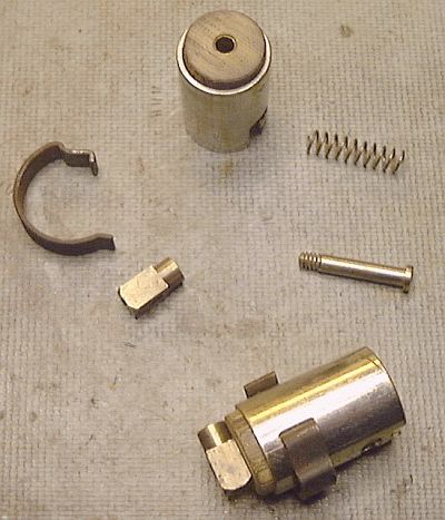
The electrical restoration also included restoring the connectors and sockets for the headlight and tail light. Pictured at the lower right is an assembled headlight connector after restoration. The upper portion of the photograph shows the components which make up a socket assembly. The fiber disk at the base of the socket was remanufactured as the old disks had deteriorated with age and the effects of heat from the lamp. The original brass contact (long screw), spring, and wire connector (the small rectangular block) were all able to be cleaned and reused. When installed the socket slides into a cavity at the back of the lamp's reflector and the spring clip shown holed the socket securely in the reflector.
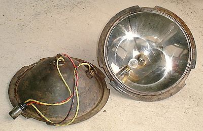
The photograph above shows the restored lamp sockets mounted in the headlamp reflectors. The reflectors are highly polished nickel plated steel. The lamp at the center of the reflector serves as the high beam lamp while the lamp mounted at the side of the reflector is the low beam driving lamp. The headlight lens is a simple Fresnel Lens and provides for a wide dispersion of light at the front of the car. By changing to a 12-volt electrical system a greater selection of high intensity lamps is available. The photograph shows the individual conductors for each lamp socket. Note the dedicated negative ground return conductors (yellow with green stripe) for each lamp socket. Originally the lamp socket was grounded through the reflector, headlamp housing, headlamp mounting, and the car's frame. A poor connection in any part of the electrical circuit transforms to problems with the lamps intensity. With the installation of dedicated negative return conductors electrical problems should be greatly reduced. Also shown in the photograph above is the four-circuit connector (shown at the bottom left of the photo) that is mounted in the rear of the headlight housing. The headlight housing connector allows the headlight to be removed from the vehicle to permit better access to the hood area of the car for boiler servicing.
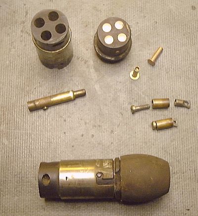
The configuration of the headlamp connector draws on the design of double post bayonet lamp base design. The plug is pushed into the socket and given a slight turn to latch it in position just like an automotive lamp is installed in its socket. Each headlight had a four-circuit connector at the back of the headlight assembly. One circuit was for the low-beam lamp's positive conductor while the second circuit was for the high-beam lamp's positive conductor. The third circuit was for each lamps negative or return conductor (both lamps used the same contact). The fourth circuit was not used. As part of the restoration each lamp's negative return conductor was given a dedicated circuit in the connector to improve reliability thus using all four circuits after restoration. At the bottom of the photograph is a complete connector. The left portion of the assembly is the socket (metal cylindrical section) which is mounted in the headlight shell. From the rear of the socket individual conductors are routed to the two light sockets of the headlight. The connector's plug right bulbous section of bakelite is attached to a length of flexible metal conduit. The components of the connector and socket are shown at the top of the photograph. The socket (upper left) contained spring-loaded contacts that were held in place by the wire clamping screw. As the bakelite the contacts were mounted in was in poor condition, it was replaced. The connector shell and spring-contacts were cleaned up and reused however the wire clamping screws were replaced with a slightly larger cap screw for easier servicing. The components of the plug are shown at the upper right in the photograph. At the middle right of the photograph are the contact assemblies for each circuit. The conductor was pushed through the bakelite insulator, pulled through the loop of the contact's "nut", the wire and nut were pushed in the barrel of the contact and the screw was tightened to draw the wire and nut inside the barrel. This made for a very poor connection at the end of a flexing cable and proved to be a very poor and highly troublesome design.
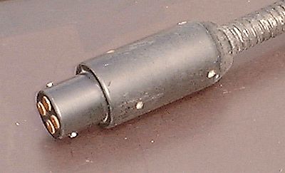
The plug was redesigned to be more robust. The new plug was machined out of black Delrin. The contacts were changed to simple brass rivets that are soldered to the ends of the stranded conductors. The housing was extended to allow it to securely clamp the 3/8" diameter flexible conduit. With the original connector's short housing the flexible conduit would detach exposing the circuit conductors. The cable would flex and place strain on the contacts which are clamped to the end of the conductors. The connection would eventually fail and could short out (remember the original wiring only had a single 20-ampere fuse protecting everything!). A similar plug was made for the tail light with the exception being that it was a two-circuit plug (grounding is through the plug's metal socket design). The new plugs, while not original Stanley in design, improve the reliability and safety of the headlight and tail light circuits. |