|
A condensing Stanley Motor Carriage has six piping systems; pilot fuel, burner fuel, water, steam cylinder oil, high-pressure steam, and exhaust steam. They operate on pressures between atmospheric (kerosene tank to the fuel pump) and 600 PSIG for the steam lines. Most of the piping systems are soft copper with the engine steam supply piping, main burner vaporizer, and superheater all being heavy-walled pipe.
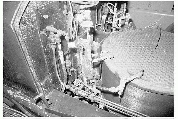
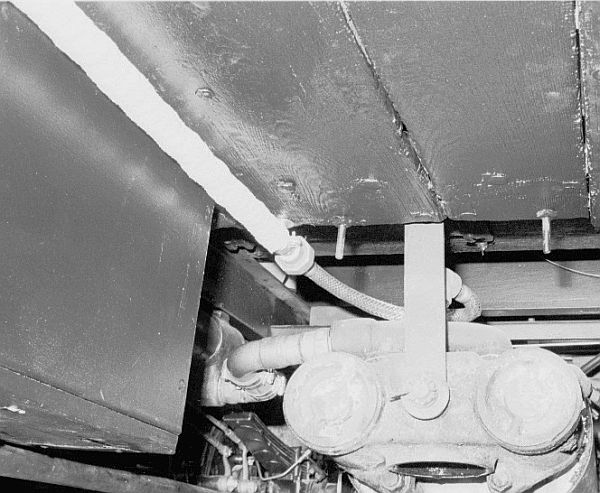
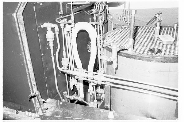
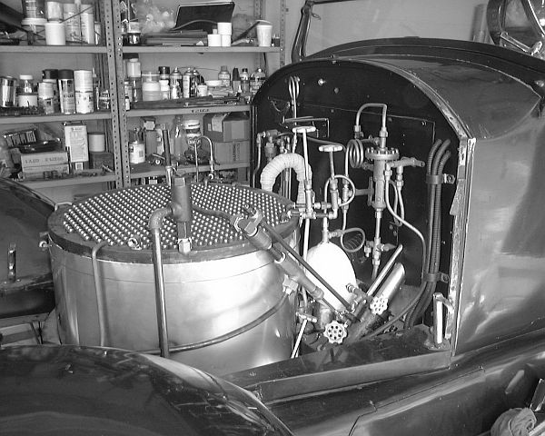
Original Right-side Plumbing Under The Hood
All six piping were restored on the car with all pumps, automatics, and valves disassembled and rebuilt. All piping was replaced with new piping where possible. The condition of the piping systems was anything but "Factory Stanley” when the car was purchased. A mix of stainless steel, black iron, galvanized steel, and assorted copper tubing sizes was located throughout the car. Additionally many valves had been added and the assortment included stainless steel, galvanized, and brass valves of gate, needle, and ball designs. If this wasn’t enough, often pipe sizes were increased or decreased along a given pipe routing to make use of available fittings and pipe sizes.
Having the Tom Marshall collection of Stanley Steam Carriages in near-factory condition made restoration of the piping systems a lot simpler to perform. Original Stanley documentation explaining how to operate the car includes excellent pen and ink drawings depicting the components under hood of a Stanley. The replacement tubing and piping was installed to duplicate original Stanley routing and design as close as possible.
The piping of the car was sketched out and compared with what Stanley detailed in their piping diagrams. These sketches were also compared to the piping of a Model 735 in the Marshall Collection to determine proper piping routing. The additions made to the car's factory piping plan include a steam blower and additional boiler blow-down valves at the base of the boiler.
Reproduction Stanley Valves A - Triple-port valve disassembled B - Dual-port valve (Late Non-Condensers & Early Condensers) C - Large Packing Nut Style Valves D - Firewall Valve E - Early Non-condensing Era Stanley Valve F - Late Condensing Era Valve
Most of the original Stanley valves that still existed on the car could be restored and reused. For valves that were beyond restoration, excellent reproduction valves are available. All original Stanley valves were completely disassembled and the packing cleaned from the packing glands and nuts. If the conical valve stem and mating valve seat needed to be relapped, this was done as well.
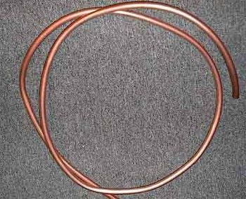
Copper pipe is sized according to it's inside diameter which varies slightly depending on the thickness of the wall. The outside dimension is always 1/8" more than the stated size. Stanley used soft copper tubing (Type K) for most of the plumbing lines on their cars. As shipped from the factory 3/16" ID was used for most air lines; 5/16" ID was used to supply the Pilot with fuel; 9/32" ID tubing was used for the burner fuel; the water lines from the pumps to the boiler check were 7/16" ID. Rare sizes in today's market place for sure. Additionally some tubing found on Stanleys wasn't copper but was brass ~ in particular the 9/32" ID tubing. Today the most common sizes of copper tubing available are 1/4", 5/16", 3/8" and 1/2" ID sizes. For those wanting to duplicate the original Stanley tubing sizes the only alternative is to use either stainless steel or aluminum tubing both of which are non-Stanley materials. For these small diameters of soft copper tubing the working pressure ratings are well above the normal operating pressure of the boiler. The following are working pressures for copper tubing; 1/4" - 1400 PSIG; 5/16" - 1200 PSIG; 3/8" - 1000 PSIG. The heavy-wall refrigeration grade tubing is often selected.
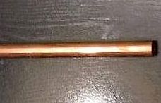
Hard Copper Tubing - Type M
Hard copper tubing (Type M) is available in 3/8" diameter and up and is used for the steam exhaust lines between the engine, boiler water feed preheater, condenser, and the water tank. Type M tubing is rigid and similar to the tubing used in homes for the hot and cold water distribution systems. One thing that can't be done with any of the piping is to solder it. Solder melts at nearly the temperature of the saturated steam generated by the boiler and thus after a short time the joints would come apart.
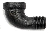
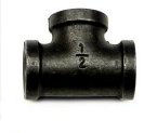
The steam line to the engine is 1/2” brass pipe. Black iron pipe in 1/8” size provided for steam connections to the top of the boiler while 1/4” black iron pipe was used for boiler connections at the bottom of the boiler. The high-pressure steam line to the throttle and superheater is 3/8” heavy-wall steel hydraulic tubing.
All pipe high-pressure steam lines from the discharge of the boiler to the engine, along with the water level indicator body, were insulated with several layers of felt ceramic fiber insulation. This form of insulation is spun from Alumina (Al2O3) and Silica (SiO2) and is available in various forms including blankets, felt, and paper. While there are numerous high temperature adhesives available to secure insulation blankets and tapes in place, simple heavy-duty wall paper paste works well, is inexpensive, and is what the Stanley's used originally. The felt ceramic fiber insulation was cut into strips, soaked in a 50-50 mix of standard and vinyl wallpaper pastes, and wrapped around each steam line. When dry another layer was added. Finally to protect the rather fragile felt ceramic fiber insulation, automotive header wrap which is a woven, high-temperature, insulation was dipped in the wallpaper paste and applied over the ceramic fiber insulation. In addition to the steam lines being insulated, the boiler, burner walls, and smokebox are all insulated with ceramic fiber insulations.
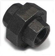
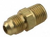
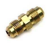
Stanley used SAE 45-degree flare-fittings for all tubing connections. While compression fittings (fittings that have a small ferrule that slips over the end of the pipe and bites into the pipe's outer surface when the compression nut is tightened) are perhaps more common, for high pressure and high vibration applications the flare fitting is the better choice. Many of the car's original fittings had been replaced while others were in very poor condition. To insure reliability all flare fittings were replaced with fittings similar to the originals. The basic difference between original Stanley flare fitting nuts and what is available today is in the shape of the flare nut. The original Stanley nuts were shorter while today's longer length nut provides better support for the tubing as it attaches to the fitting thus reducing fatigue.
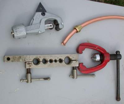
Flared fittings can only be used with soft (flexible) copper tubing The tubing is cut with a pipe cutter (upper left above) and the flare nut is slid onto the tubing. The tubing end is clamped in a flaring tool (lower left with holes) and a flaring tool (lower right) flares the tubing end. The tubing and nut is then placed on the fitting and tightened with a special pair of tubing wrenches.
For items such as the water, fuel, and oil pumps, each pump was disassembled, all packing replaced, and the integral check-valves cleaned and tested to insure they seated properly. For the automatics such as the water automatic, steam automatic, and low water automatic each automatic was disassembled, cleaned, and packings replaced before reassembly and testing. The dash gauges were tested for accuracy throughout their nominal display ranges.
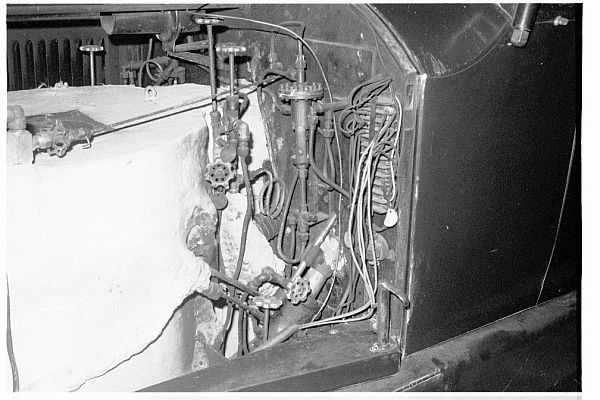
Left Side Under The Hood ~ New Piping and Boiler
Before the piping systems were pressurized with their working fluids (kerosene and hexane in particular) everything was pressure tested. For these tests the Stanley dash gauges were disconnected and the lines attached to test gauges as damage to the Stanley gauges was to be avoided). The kerosene system was pressurized to 200 PSIG (working pressure of 140 PSIG) and the pilot fuel system was pressurized to 50 PSIG (working pressure of 20 PSIG). These pressure tests were done with air since the pressures were low and the system volumes small. While the test pressures bled down slowly due to packing leakage it proved the plumbing sound and that when pressurized with kerosene or hexane that a high pressure leak which would squirt fuel was probably not likely.
While the boiler had been tested to 1000 PSIG right after manufacture, once installed it was pressurized (called a hydrostatic test) to 800 PSIG to insure the integrity of the piping, etc. The boiler testing was done by filling the boiler full of water and then placing the water under pressure with a hand pump and looking for leaks. Once the fuel, water, and steam piping systems had passed their respective tests they were ready for the initial firing up of the burner. |