|
The overall condition of the Warner steering system on the car was quite good. There really wasn't any "restoration" work required. The steering had a lot of "looseness" in it but that was tracked to the steering box and how things were adjusted. Additionally there seemed to be a lot of resistance in turning the steering wheel which was probably due to old grease that had become hard. As it had been some time since the steering box had probably been maintained due to what is required to remove it, the restoration was really opening things up, cleaning out old grease, and putting things back together again.
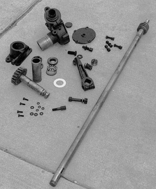
Pictured above are all the parts of the steering box. With the boiler out of the car for replacement, access to the steering box was very easy. Removal of the steering box for servicing requires sufficient space to move the steering box towards the center of the car so that the output shaft can clear the frame while sliding the steering shaft and steering tube out of the opening in the firewall. With the boiler out of the way removal of the steering box can be done. Upon opening up the unit much of the grease was found to be hard so through cleaning of all parts in the parts cleaner was necessary. Inspection of all the parts indicated that nothing was worn excessively. The bearings were found to be in excellent condition so they were not replaced but just packed with new grease.
As shown in the above photograph, the steering box is quite simple. The worm gear is pressed and pinned onto the steering column shaft (horizontal in the photo). The worm gear mates with the sector gear which has an integral shaft that serves as the output from the steering box. The play of the worm gear in and out of the steering box is adjusted by adjusting nuts associated with the steering column as it passes through the steering box casting.
The sector gear shaft runs through an eccentric tube and the two pieces slide through an extension that is part of the steering box casting. The end of the sector gear shaft is square for the attachment of the crank arm (shown in the lower left of the photograph). By rotating the eccentric tube the sector gear can be adjusted with respect to the worm gear. A bolt on the gear box cover adjusts the play of the sector gear. Between the adjustments for the play of the steering shaft and worm gear, the eccentric tube adjustment for the sector gear, and the bolt in the gear box case cover, all of the play can be adjusted out of the steering system between the steering wheel and the crank arm.
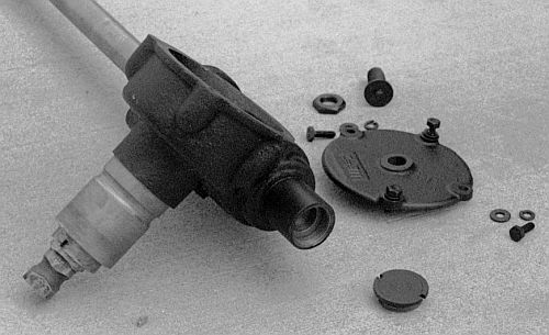
Pictured above is the steering column tube that the steering column shaft rotates inside and the wooden steering wheel. The thin, long shaft, black-handled lever, and quadrant (left center of picture) are the throttle lever and shaft and the quadrant that it moves on. The quadrant clamps to the steering column tube. The bracket at the right center of the photography is the bracket that holds the assembly to the dash.
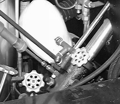
The steering box is located on the boiler side of the firewall at the left side of the car. The throttle control shaft is mounted on top of the steering column and is mechanically linked to the throttle. The valves around the steering box are blow down valves for the boiler and kidney water level indicator (white insulated unit in the photograph above). It is obvious from this picture how crowded things are in this area under the hood and why when the boiler is out an excellent opportunity to service the steering box is provided.
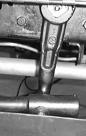
Pictured above is the crank arm which changes the rotational motion from the steering wheel into linear motion to turn the front wheels and steer the car. The square end of the sector gear shaft mates with the square opening in the crank arm (top of photograph). A ball at the opposite end of the crank arm mates with a recess in the drag link rod at the bottom of the photograph. The drag link rod transfers motion from the crank arm to the front wheels. Sometime in the past the crank arm was shortened as evidenced by the welding at the midpoint of the crank arm (just below the Wagner logo). This was done to make turning the steering wheel easier. Shortening the crank arm also means it takes more steering wheel motion to turn the wheels a given distance.
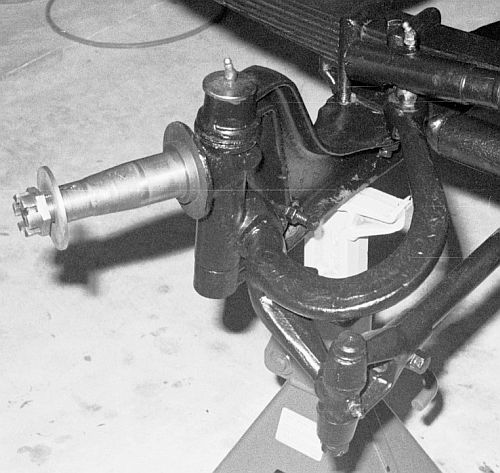
The drag link rod from the crank arm connects to a curved arm that is part of the front left wheel assembly. Also connected below this arm is a second shorter arm that allows connection of a link interconnecting the right and left front wheels so that they turn together. The king pins for both front wheels were not worn and thus did not require any attention other than greasing. Shown in this picture is the left front wheel axle with the wheel hub removed. The wheel hubs were removed and the bearings removed, the bearings cleaned of old grease, inspected for damage, and packed with fresh high-temperature grease. Felt seals up against the inside of the hub were replaced to insure the new grease didn't become contaminated.
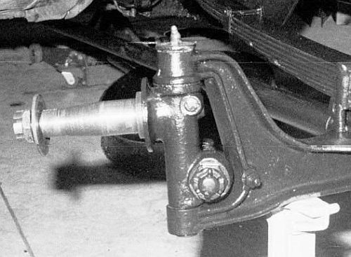
The right front wheel hub had it's bearings cleaned, inspected, and greased similar to what was done for the left front wheel. The king pin was greased and the felt seal replaced. With all this work complete the steering system restoration was complete. The excess motion of the steering system was gone and with new grease in all components the car was easier to steer. With new larger tires a further improvement in steering was realized. |