|
The level indicators for the kerosene and pilot fuel tanks as well as the water tank were manufactured by Boston Auto Gage Company of Pittsfield, Massachusetts. The gauge in the water tank had been replaced many years ago with a military style gauge. That gauge was retained when the new tank was manufactured. In the spare parts that came with the car when it was purchased was a Boston gage that was able to be used for parts.
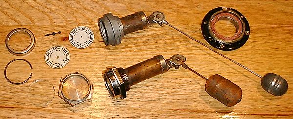
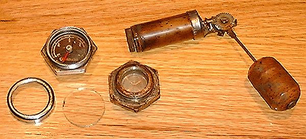
Pictured above are the kerosene fuel tank (long float lever) and the pilot fuel tank (shorter float level) gauges assembled after restoration. To the left in the photograph are the dial faces, one of the dial needles, as well as the glass bezel and retaining rings for the bezel. The nickel-plated body of the pilot fuel tank gauge (smaller float arm ~ center) is hexagonal with the dial on one side while the float mechanism mounts to the opposite side (inside of the tank). The body is treaded such that it will thread into a nipple welded into the top surface of the pilot tank. While the pilot fuel tank gauge is threaded into a nipple welded on the top of the pilot fuel tank, the mounting of the kerosene tank level gauge is a bit different. The gauge body is circular and slips into a brass mounting ring that is fastened to the right side of the tank (black ring with red gasket shown at the upper right of the top photograph). For both gauges the float mechanism is mounted to the "inside" or tank side of the gauge body. The float mechanism consists of a large copper tube with it's ends capped. It is finely threaded on one end and threads into a well in the gauge body. The opposite end includes an L-shaped bracket for mounting of the float arm. In the photograph below the back side of the pilot fuel tank gauge body is shown near the center of the photo. At the upper right is the float mechanism with the copper cylinder that threads into the gauge body.
The copper cylinder has a hole drilled in either end and a brass shaft passes through the holes. At the gauge body end of the cylinder a magnet is mounted to the brass shaft. When the copper cylinder is screwed into the gauge body the magnet turns in a recess within the gauge body. The magnet rotates next to the wall of the gauge body so that the magnetic flux will pass though the wall to the gauge needle mounded on the opposite side. The opposite end of the brass shaft has a pinion gear attached. The pinion gear meshes with a gear which is rotated by the action of the gauge float working through a lever arm. The linear motion of the float resting on the top of the fuel is transformed into rotary motion of the float gear. The gear is mated to a pinion which rotates the brass shaft in response to the movement of the float. The magnet attached to the opposite end of the shaft rotates with the shaft. The complete float mechanism being mounted to the "inside" of the gauge body is exposed to the fuel. All of the components are non-sparking being made of copper, brass, or pot metal. Also shown in the photograph above is the dial side of the gauge body. The gauge body is made of brass which is non-magnetic. A round copper disk marked with tank level graduations is installed in the brass body and a needle floats on a pin secured in the center of the copper disk. A glass disk is installed over the dial and needle to keep the needle from coming off and a cap screws over the body and keeps the assembly together. As the float moves and transmits it's motion to rotational motion of the magnet, magnetic coupling to the needle rotates the needle to indicate the tank's level. The brass construction of the gauge body and the copper construction of the dial do not affect the magnetic flux between the magnet located on the inside of the tank and the needle mounted on the outside of the tank. A similar principal is used for the boiler water level indicator located on the firewall. |