|
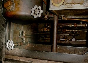
The above photo
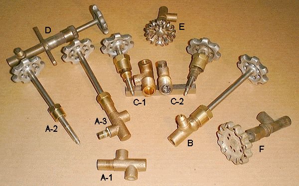
shows an assortment of Stanley valves. Perhaps the most common of the
Stanley valves is the style shown as A-3. This style valve consists of
a brass base (A-1) which comes in a number of port configurations. The
valve stem (A-2) screws into the valve base and the packing nut shown on the
valve stem tightens onto the valve base to seal the valve. For this
style valve 1/8" square graphite impregnated packing is pushed into the
packing nut between the walls of the packing nut and the valve stem.
Generally only two rounds of packing can be placed in the nut. As the
packing nut is tightened down the packing is compressed to seal against the
shaft and keep the valve from leaking at the stem.
An alternate valve style is shown at
B. This style valve was larger than the valve style just discussed and
included a packing stuffing box as part of the valve body. A close
examination of the two valves C-1 and C-2 show the packing stuffing box
without packing (C-1) and with packing (C-2). You'll also note the
packing gland on the valve stem just below the packing nut. With the
valve stem installed in the valve body two rounds of 1/8" square graphite
impregnated packing is placed in the stuffing box. The packing gland
is pushed down into the stuffing box and the packing nut tightened to
compress the packing against the valve stem to prevent leaking.
The valve style shown in D is
representative of the valves used on the car's firewall. A hole the
diameter of the valve body is drilled in the firewall and the valve body is
inserted from the boiler side of the firewall and secured by screws in the
valve body ears (yes, Stanley firewall construction was wood with a tin
covering on the boiler side of the firewall). The valve stem, packing,
packing gland, and packing nut were all installed on the valve body from the
dash side of the firewall. The valve shown still has remnants of
nickel plating which these valves often had to dress them up were seen by
passengers.
Valve E shows the lace pattern valve wheel which was punched and formed from
sheetmetal before being nickel plated. These valves were used on the
early Stanley cars. Much more common were the valve
wheels of cast aluminum construction. An alternate valve handle
design was a wire spring wrapped around a metal hub on the very first cars
or the stamped valve wheel found on the last few years of condenser car
production. Stanley valve
stem ends were machined with a 1/4" square so that the valve wheel could be peened onto valve stem.
Stanley valve ports were generally
tapped to accept 1/8"-27 NTP pipe as most of the examples above depict.
By mounting the valve to a pipe it allowed the pipe to provide support to
the valve. The remaining ports could be made with pipe connections or
have a flare compression fitting used. Some valves were cast with
integral flare fittings cast into the valve body as shown in B. The
45º flare at the end of the fitting required that the tubing be flared to
the same 45º angle. When the fitting nut is
tightened it compresses the tubing between the flare on the nut and the
flare on the fitting thus providing a clamping action between the tubing and
the fitting. This form of fitting provides increased strength to the
connection and insures a large contact surface between the tubing and the
fitting allowing the fitting to withstand high pressures and vibration.
See the discussion on the Pilot
Valve for additional information on Stanley valves including a discussion on
packing valves and pumps. See the discussion of the Boiler Check Valve
for a description of the design and operation of Stanley check valves.
See the article on the Fuel Pressure Relief Valve for a additional
discussion on Stanley valves. See the article on the Burner Fuel
System Strainer, Check Valve, and Shut-off for a discussion of the pipe and
copper tubing used on Stanley cars. |