|
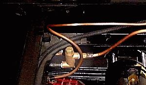
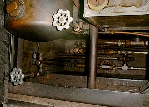
Under the hood a Stanley car is a maze
of black malleable or forged steel and iron pipe along with an assortment of
copper tubing. Black iron pipe is used around the bottom of the boiler for
blow-down lines and where support of a valve or other device is needed.
Either 1/4", 3/8", and a limited amount of 1/2" pipe is used. The use of
galvanized pipe, stainless steel pipe, and brass pipe is not recommended for
steam service for various reasons. With the heat and pressures present pipe
used for boiler connections should be Schedule 80 minimum with Schedule 40
being used for all other connections.
  Stanley cars contain many feet of
copper tubing and a vast assortment of SAE 45-degree flare fittings.
Copper pipe is sized according to it's
inside diameter which varies slightly depending on the thickness of the wall.
The outside dimension is always 1/8" more than the stated size.
Soft copper tubing that is easily formed with a tubing bender is used for
water, fuel, and steam on a Stanley. As shipped from the factory
3/16" ID was used for most air lines; 5/16" ID was used to supply the Pilot
with fuel; 9/32" ID tubing was used for the burner fuel; the water
lines from the pumps to the boiler check were 7/16" ID. Rare sizes in
today's market place for sure. Additionally some tubing found on
Stanleys wasn't copper but was brass ~ in particular the 9/32" ID tubing. Stanley cars contain many feet of
copper tubing and a vast assortment of SAE 45-degree flare fittings.
Copper pipe is sized according to it's
inside diameter which varies slightly depending on the thickness of the wall.
The outside dimension is always 1/8" more than the stated size.
Soft copper tubing that is easily formed with a tubing bender is used for
water, fuel, and steam on a Stanley. As shipped from the factory
3/16" ID was used for most air lines; 5/16" ID was used to supply the Pilot
with fuel; 9/32" ID tubing was used for the burner fuel; the water
lines from the pumps to the boiler check were 7/16" ID. Rare sizes in
today's market place for sure. Additionally some tubing found on
Stanleys wasn't copper but was brass ~ in particular the 9/32" ID tubing.
Today the most common sizes of copper tubing available are 1/4", 5/16", 3/8"
and 1/2" ID sizes. For those wanting to duplicate the original Stanley
tubing sizes the only alternative is to use either stainless steel or
aluminum tubing both of which are non-Stanley materials. For these
small diameters of soft copper tubing the working pressure ratings are well
above the normal operating pressure of the boiler. The following are working
pressures for copper tubing; 1/4" - 1400 PSIG; 5/16" - 1200 PSIG; 3/8" -
1000 PSIG. The heavy-wall refrigeration grade tubing is often
selected.
 For some applications such as the
steam line to the rear of the car or for the feed water heater water line
copper piping is used. Coppering piping is durable and is available in three
basic grades. Type M is the most basic grade, is thin-walled, and is marked
for identification with red lettering. Type L is about twice as strong as
type M and is marked with blue lettering. Type K is the strongest and is
recommended for use with a Stanley even though it is the most expensive.
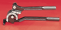
Type K is marked with orange lettering. Tubing should never be bent by
hand as the softness of the copper walls make the tubing prone to kinking.
The best way to make uniform, smooth bends with copper tubing and pipe is to
use the proper tubing bender (shown at left) or pipe bender (such as an
electrician's conduit bender). For some applications such as the
steam line to the rear of the car or for the feed water heater water line
copper piping is used. Coppering piping is durable and is available in three
basic grades. Type M is the most basic grade, is thin-walled, and is marked
for identification with red lettering. Type L is about twice as strong as
type M and is marked with blue lettering. Type K is the strongest and is
recommended for use with a Stanley even though it is the most expensive.
Type K is marked with orange lettering. Tubing should never be bent by
hand as the softness of the copper walls make the tubing prone to kinking.
The best way to make uniform, smooth bends with copper tubing and pipe is to
use the proper tubing bender (shown at left) or pipe bender (such as an
electrician's conduit bender).
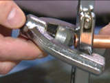
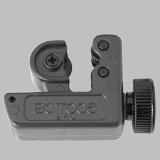 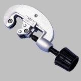 A tubing cutter
(shown at right) is the best tool for cutting copper tubing
and pipe. The cutter is placed on the tubing or pipe and rotated around the
tubing or pipe to cut it. Turning the handle to tighten the blade against
the pipe or tubing as you twist the cutter around the pipe in a circular
motion cuts through the tubing or pipe. Several turns are usually sufficient
to cut through the tubing or pipe. Most cutters also include a reamer
tool--a short blade used to remove metal burrs after the pipe has been cut.
Sometimes for tight spaces a mini-cutter (shown at left) can be handy. A tubing cutter
(shown at right) is the best tool for cutting copper tubing
and pipe. The cutter is placed on the tubing or pipe and rotated around the
tubing or pipe to cut it. Turning the handle to tighten the blade against
the pipe or tubing as you twist the cutter around the pipe in a circular
motion cuts through the tubing or pipe. Several turns are usually sufficient
to cut through the tubing or pipe. Most cutters also include a reamer
tool--a short blade used to remove metal burrs after the pipe has been cut.
Sometimes for tight spaces a mini-cutter (shown at left) can be handy.
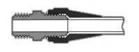
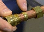
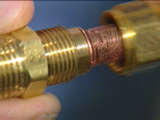
For
connecting soft copper tubing to valves and automatics special fittings are
used. While compression fittings (shown below at left) may seem applicable (and
could be used in an emergency) the use of flare fittings (shown below at right)
are recommended. A flare fitting consists of a flare nut and flare body.
There's no ferrule because the copper pipe flares out, forming a lip that is
sandwiched between the nut and body. Solid brass flare fittings create a
stronger connection than can be achieved with soldered or compression
fittings. The long flare nuts provide extra support and vibration resistance
to the connection. Flaring the pipe requires a specialized tool.
 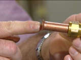 In order to properly
install a flare fitting, cut the tubing to the desired length. Remove any
burrs from the tubing ends, and slide the flare nut onto the pipe. Push the
flare nut back far enough on the tubing so that it will be out of the way
when you use the flaring tool. Clip the pipe
in the flaring tool, keeping the end flush with the face of the tool. Slowly
turn the handle on the tool until it bottoms out making a bell end at the
end of the copper tubing in the flaring tool. Unscrew the handle and remove
the tool to check the quality of the flare. A properly flared tubing end is
smooth and evenly bell shaped. Mate the tubing to the flare fitting body and
hand-tighten the flare nut. Proper tightening of a flare fitting requires
two wrenches, one on the flare fitting’s body and the other on the flare
fitting’s nut. The wrench on the fare fitting’s body keeps it from turning
while the nut is tightened. In order to properly
install a flare fitting, cut the tubing to the desired length. Remove any
burrs from the tubing ends, and slide the flare nut onto the pipe. Push the
flare nut back far enough on the tubing so that it will be out of the way
when you use the flaring tool. Clip the pipe
in the flaring tool, keeping the end flush with the face of the tool. Slowly
turn the handle on the tool until it bottoms out making a bell end at the
end of the copper tubing in the flaring tool. Unscrew the handle and remove
the tool to check the quality of the flare. A properly flared tubing end is
smooth and evenly bell shaped. Mate the tubing to the flare fitting body and
hand-tighten the flare nut. Proper tightening of a flare fitting requires
two wrenches, one on the flare fitting’s body and the other on the flare
fitting’s nut. The wrench on the fare fitting’s body keeps it from turning
while the nut is tightened.
Click on the following link for a portable document format (PDF) version of
the
Parker Flared Fittings Catalog.
Additional specifications on copper tubing and information
relating to piping may be obtained at
http://piping.copper.org/
See the discussion on the Pilot
Valve and the Fuel Pressure Relief Valve for additional information on Stanley valves including a discussion on
packing valves and pumps. See the discussion of the Boiler Check Valve
for a description of the design and operation of Stanley check valves. |