(this page takes a couple minutes to load)
|
(this page takes a couple minutes to load) |
|
The HOW IT WORKS section of this web site is navigated from a main screen. Part of the main screen is a diagram of the plumbing system for a Stanley Model 735 Motor Carriage. Use the curser to point and click on any component on that diagram and the diagram will be replace with a discussion on the component just selected. A listing of the components of a Stanley Motor Carriage, arranged by system, is also provided as an alternate way to navigate through the web site. Using your browser's "back" button or the link at the bottom of each page returns you to the main diagram. More detailed instructions and tips for navigating this section of the web site are provided below. This site may be viewed with either Netscape Navigator or Microsoft internet Explorer. The site is best viewed with a screen resolution of 1024 x 768 dots per inch (DPI) and at least 256 colors. This section will continually be upgraded with new information so stop back regularly to see what is new. If you have problems viewing the site or have suggestions for improvement please send an email to the website owner by clicking the email icon at the bottom of this page.. Please review the DISCLAIMERS & COPYRIGHT page for important information regarding use of the material on this web site.. Click the link at the very bottom of the page to proceed to "HOW IT WORKS". |
|
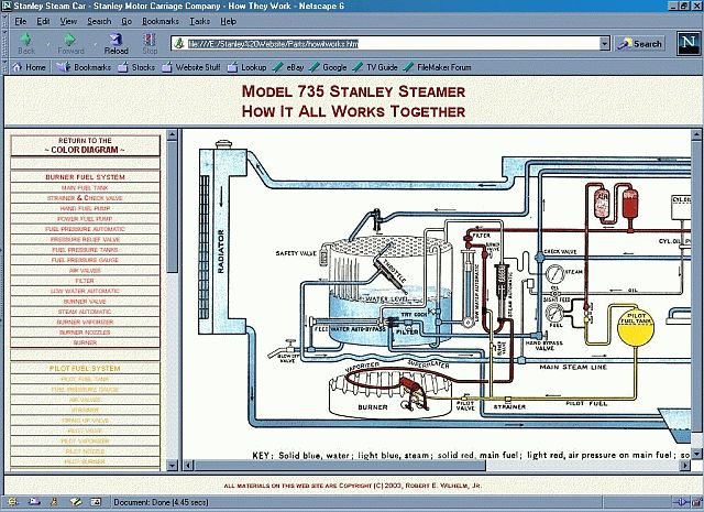
the main navigation screen |
|
From this screen the web site visitor can navigate to nearly 50 detailed discussions related to the design, construction, operation, and functionality of the Stanley Motor Carriage or steam car. The diagram at the right depicts the five major piping systems on a Stanley Motor Carriage; pilot fuel, burner fuel, boiler water, steam, and engine lubrication. On the left is a tabular listing, by piping system, of each component shown on the piping diagram. Each piping system is color coded on the piping diagram and in the tabular listing as follows; Pilot Fuel ~ Yellow, Burner Fuel ~ Red, Boiler Water ~ Dark Blue, Steam ~ Light Blue, and Engine Lubrication ~ White in the diagram and Brown on the tabular listing, As there are some components on the car that are not shown in the piping diagram they are included as a separate tabular listing, in Green. As you view each of the component pages the background color of the page will match the piping system it is associated with. Thus the page background for all components associated with the Pilot Fuel System for example will be yellow. For those components which bridge two systems the background is the same as this page (cream). |
|
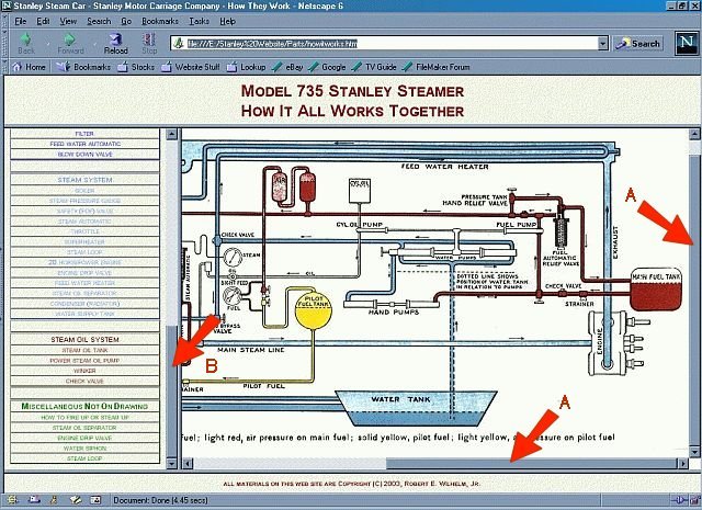
navigation bars |
|
To maintain the readability of the piping diagram it has been kept large in size thus only part of it will be shown on the screen at any given time. Two navigation bars (labeled as "A" in the photo above) are provided to allow the piping diagram to be shifted within the frame. In the photo above the piping diagram has been shifted to the lower right corner through the movement of the two navigation bars, "A". The tabular listing of components is also longer than can be displayed on the screen. A navigation bar (labeled as "B" in the photo above) is provided to allow viewing of the complete tabular listing of components. In the photo above the tabular listing has been shifted to view the bottom entries through the movement of navigation bar "B". |
|
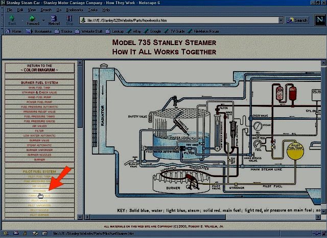
selecting a component in the diagram |
|
To select a component to view on the piping diagram, move the curser over the item you wish to view as shown by the red arrow in the photo above. Click the mouse and the piping diagram will change to display the information on the component selected. Microsoft Internet Explorer users will see a descriptive box pop up for each component as it is viewed to aid in the selection of a component for viewing (this feature is not fully functional with Netscape Navigator). The information on the component selected will replace the piping diagram initially displayed. The navigation bar between the tabular listing of parts and the piping diagram can be moved to the left to provide more room for the display of the piping diagram and the component discussions. The navigation bar can be moved back to the right if access to the tabular listing is desired. When you've finished reading the material on the selected component there are three ways to return to the piping diagram for selecting another component. As you will be at the bottom of the component page, a link back to the piping diagram is provided. Simply click the link and the component information will be replaced with the piping diagram. The browser BACK button may be selected to return to the piping diagram. At the top of the tabular listing is a link back to the piping diagram which may be used as well. |
|
selecting a component using the tabular listing |
|
As an alternate to using the piping diagram to select components the tabular listing may be used. Within the tabular listing the components are grouped by the piping system they are associated with. Additionally the components are listed in the order of fluid flow of the piping system (the burner fuel system components for example are listed from the fuel supply tank through to the burner). To select a component to view in the tabular listing, move the curser over the item you wish to view as shown by the red arrow in the photo above. Click the mouse and the diagram will change to display the information on the component selected. When you've finished reading the material on the selected component there are three ways to return to the piping diagram to select another component. As you will be at the bottom of the component page, a link back to the piping diagram is provided. Simply click the link and the component information will be replaced with the piping diagram. The browser BACK button may be selected to return to the piping diagram. At the top of the tabular listing is a link back to the piping diagram which may be used as well. |
|
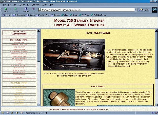
component information screen |
|
The component information screen is broken down into two major sections. At the top of the page is a photo of the component and a brief description of the component's function and use. For those wishing more in-depth information on the component a longer discussion is provided. The photo above shows the Pilot Fuel Strainer screen replacing the piping diagram. The photo shows the component being discussed as a brighter area than the rest of the photograph to make it easier to locate. Under the photo is an indication of where on the car the component is located. To the right of the photograph is some basic information about the component. The detailed discussion at the bottom of the page provides an in-depth description of how the component works, how it fits in with the operation of the car, and other pertinent information. Supplemental drawings and photographs will be found here to help the reader gain a full understanding about the component. Where applicable, information related to troubleshooting, maintenance, and repair of the component is included. |
click here to go on to "how it works"
Questions or Comments? Please email me!
BACK
![]()
![]() FORWARD
FORWARD