|
A Stanley pilot,
also referred to as a pilot burner by Stanley, is known as a vaporizing
pilot or vaporizing burner. Perhaps the closest cousin of the Stanley
pilot burner are the Coleman Camp stoves with operate on similar principals.
The pilot burner functions similar to a Bunsen burner or a modern propane
torch in burning gaseous fuel with the
exception that the pilot burner operates from liquid fuel that must be
vaporized into a gaseous state. A Bunsen burner forces fuel that is
already in a gaseous state through a very small orifice and into a vertical
cylindrical chamber that forms the body of the Bunsen burner. Air is
admitted to the cylindrical chamber alongside the gas stream and the air and
fuel mixture rises through the cylindrical chamber to a horizontal screen at
the end of the chamber where combustion can occur on the upper surface of
the screen.
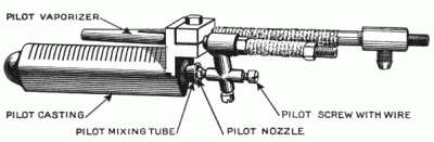
The main part of the pilot is the
pilot casting which is very close in size to the cardboard tube found inside
a roll of bathroom tissue. As shown in the diagram above, thin slots
are machine-cut into the upper side of the pilot casting and extend through the
wall thickness of the casting to the interior chamber. The casting is
hollow with a hole in it at the nozzle end and closed off at the opposite
end. Inserted
into the opening in the end of the pilot casting is a mixing tube.
This tube runs the length of the pilot casting located along the central
axis of the casting. The mixing tube projects from the end of the
pilot casting about a 1/4" and is flared slightly similar to a horn's bell.
This tube is open along the bottom or drilled with holes along its bottom
surface. Gas vapors in the mixing tube flow through the holes or slits
in the bottom of the mixing tube and then up and through the slits of the
pilot casting to burn on the top of the casting.
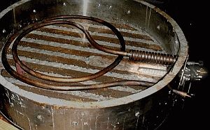
Above the pilot casting is a
U-shaped tube which vaporizes the liquid fuel supplied to the pilot.
Designed to only work with gasoline or similar fuels that are easy to
vaporize, the tube is generally 8" in length over the pilot casting.
The liquid fuel is admitted into one of the legs of the U-tube (the rear one
in the drawing) and gaseous fuel discharged from the other leg is connected
to the pilot nozzle.
In 1918 Stanley experimented with
heating the pilot by applying power from the 6-volt battery and thus both
legs of the pilot vaporizer were extended to permit the attachment of the
heavy battery leads as shown in the drawing above. Unfortunately this
attempt at providing an electric starting capability on a Stanley was not
successful due to battery construction of the period. The 6-volt
batteries of the era just couldn't stand the stresses of repeatedly
delivering high currents for short periods. Electric
starting was also problematic because the generator on early cars was only
rated at 20 amperes and turned out not to be sufficient to charge a battery
properly unless the car was used for long duration trips at a decent speed
(something the roads of the period generally did not permit). The
Stanley instructions suggested only using the electric start for 15 to 20
seconds and to drive the car 25 or 30 miles afterward to charge the battery.
The pilot nozzle is a hollow casting
that includes a cone-shaped extension that enters the mixing tube mounted in
the open end of the pilot casting. At the point of the cone is a very
small orifice (generally a #64 drill size for a Stanley pilot) for injecting
gaseous fuel into the mixing tube. The pilot nozzle includes a screw
with a 0.036" diameter wire attached to the end of the screw and projecting
through a hole in the end of the cone-shaped extension of the pilot nozzle
casting. The wire has a small flat filed into it (generally the flat
decreases the wire's diameter to 0.029" at the flat) where it passes through the pilot
nozzle's hole. By rotating the screw the wire is turned in the pilot
nozzle's hole and thus can clean any deposits out of the pilot nozzle's
hole. The
pilot is lit by taking a torch and heating the pilot nozzle casting
and the copper fuel feed tubing attached to the fuel side of the pilot vaporizer external to the burner.
When sufficiently hot (this generally requires two to three minutes of
heating) the pilot fuel valve is opened to admit fuel to the pilot.
Upon contact with the preheated fuel supply tubing and the pilot nozzle the
fuel vaporizes to a gas that flows out the small hole in the pilot nozzle
and into the mixing tube. As the fuel supply is under pressure the
gaseous fuel exiting the pilot nozzle is injected at a decent velocity down
the central axis of the mixing tube.
As the gaseous fuel moves down the mixing tube it combines with air at at
the proper air/fuel ratio for combustion to occur. The mixture flows
out the openings of the mixing tube and into the pilot nozzle casting.
The pressure differences of the mixture in the pilot casting chamber and the
outside of the pilot casting allow the air/fuel mix to flow through the
slots in the pilot casting where it is ignited and burned.
The burning air/fuel mixture creates a continuous flow of air into the
mixing tube with the gaseous fuel injected into the mixing tube by the
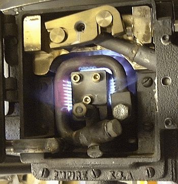
pressure on the fuel system. The burning fuel on the top side of the
pilot casting heats the vaporization tube and allows the vaporization
process to continue as fuel is fed to the pilot. A properly adjusted
and operating pilot should produce a blue flame similar to that pictured
above right.
As a pilot burns carbon deposits may
form on the wire and at the hole in the pilot nozzle. This will reduce
the gaseous fuel flow and cause the pilot to reduce its burning intensity.
This is quickly corrected by taking a screwdriver and giving the pilot
nozzle screw a half turn and then reseating it several times in rapid
succession. It is imperative that the burner access port be
closed anytime the pilot nozzle screw is moved as the screw will leak fuel
which could be ignited by the pilot's flame and thus flash into flame in the
presence of the operator. In a like manner, due to the
pressure on the pilot fuel system and the lengths of fuel tubing between the
pilot valve and burner, the pilot may continue to burn for as much as 5 or
10 minutes. Thus it is important to insure the pilot has been
extinguished before performing any maintenance on either the pilot or the
burner fuel systems. Before blowing down a boiler the operator needs
to insure the pilot is extinguished as the pilot can locally heat the bottom
of the empty boiler and damage the flues.
A proper burning pilot should be
blue with very little to no yellow present. The appearance of yellow
in the flame indicates that the air/fuel mixture is not proper for
combustion. The yellow condition may be corrected by changing the
pressure carried on the pilot tank (generally the pressure should be
somewhere between 20 and 30 PSIG). If the flat on the wire is too
small or too large an improper air/fuel mixture will result and cause the
flame to show yellow. If the mixing tube is blocked or otherwise
damaged an improper air/fuel ratio or insufficient mixing will occur and the
flame will show yellow color.
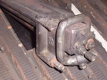
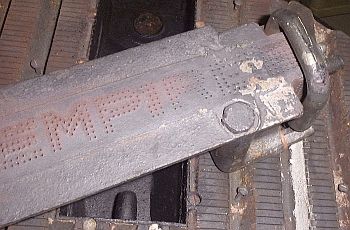
There were several manufactures that
produced aftermarket pilots for Stanley steam cars. Perhaps the best
known was the Cruban pilot. Manufactured by the Empire Burner Company
in New York, the Cruban pilot for a Stanley burner included an extension to
the mixing tube that Empire claimed would keep the pilot's flame from being
extinguished when driving the car. Empire also manufactured a complete
burner assembly for Stanleys that includes a heavy, brick-sized pilot that
was easily maintained. |