|
 Stanley
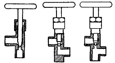
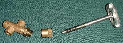
valves are very simple in their construction. They consist of a
cast brass body, valve stem, handle, and a machined brass packing nut.
The drawings at the left depict only three of nearly a dozen valve
configurations that Stanley manufactured. While the ones shown
depict valves with ports tapped for 1/8" pipe, Stanley also manufactured
valve bodies that were flared and threaded to accept 1/4" and 9/32"
copper tubing. Stanley
valves are very simple in their construction. They consist of a
cast brass body, valve stem, handle, and a machined brass packing nut.
The drawings at the left depict only three of nearly a dozen valve
configurations that Stanley manufactured. While the ones shown
depict valves with ports tapped for 1/8" pipe, Stanley also manufactured
valve bodies that were flared and threaded to accept 1/4" and 9/32"
copper tubing.
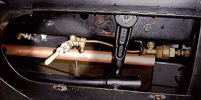
Many of the multitude
of valves necessary to operate a Stanley were located in difficult to
reach positions either physically or because they were near hot
surfaces. As a result the valve stems were made from a 1/2" length
up through several feet in length to move the valve wheel to an easier
to reach and safer position. Initially the 1/4" diameter valve
stems were made of brass but that was later changed to steel.
Today most replacement valve stems are made of stainless steel and folks
prefer the long taper over the shorter one. The end of the valve
stem is machined to a 30-degree taper all though some later Stanley
valves incorporated a 15-degree taper. The threads are 5/16" by 20
threads per inch.
See the discussion on
the Fuel Pressure Relief Valve for a photo of assorted Stanley valves
along with additional information.
One of the mistakes
often made in operating Stanley valves is to open them more than
necessary. The construction of a Stanley valve and valve seat,
with the tapered cone design, is that in two complete revolutions of the
valve handle the valve is fully open. In most cases one full
rotation of the valve handle is sufficient. There is no need to
open the valve more than two turns to achieve full flow through the
valve.
Likewise, when
closing a Stanley valve some have the tendency to apply a lot of
rotational pressure to the valve handle to insure the valve is "tightly
closed". Again, the design of the valve stem and valve seat
insures that with only a moderate amount of force the valve is closed.
Attempting to "crank down" on the valve handle not only damages the soft
brass valve seat but in the case of steam valves, when the steam valve
cools it will be nearly impossible to open the valve because the metal
components have contracted and are even more tightly bound.
In the case of
blow-down valves it is good practice to close the valve until the valve
stem and seat just mate and close off the majority of the water and
steam flow. Sometimes small bits of grit and rust can get
lodged on the valve seat during the blowing down operation. These
debris will not allow the valve stem to seat properly and if the handle
is closed tightly the debris may be ground into the soft brass valve
seat. The rotation of the valve stem on the valve seat will also
cause the debris to cut grooves in the seat which become the pathways
for the valve to leak.
A recommended
practice is to close the valve just to the valve stem reaches the valve
seat. At that point it is good practice to open the valve a
quarter turn and reseat the valve stem on the seat. If with a
little bit of pressure the valve closes then that is how it should be
left. If the valve does not close off then repeat the opening and
reseating a couple more times. Observe the end of the blown down
line connected to the valve for leaking but remember that it may appear
to be leaking when it is really the remaining steam and water in the
line draining. If the valve continues to leak then it will be
necessary to dress the valve seat and the end of the valve stem to make
a better seal.
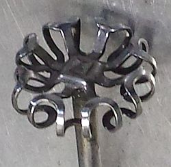 Stanley
valve handles or valve wheels were mostly of a cast aluminum
construction. However some early Stanleys (until about 1909) used
a lace pattern valve wheel (see image at left). An alternate valve
handle design was a wire spring wrapped around a metal hub.
Stanley valve stem ends were machined with a 1/4" square so that the
valve wheel could be peened onto valve stem. Stanley
valve handles or valve wheels were mostly of a cast aluminum
construction. However some early Stanleys (until about 1909) used
a lace pattern valve wheel (see image at left). An alternate valve
handle design was a wire spring wrapped around a metal hub.
Stanley valve stem ends were machined with a 1/4" square so that the
valve wheel could be peened onto valve stem.
The packing nuts for
the valves included enough space for two rings of packing to be used.
The packing was carried inside the packing nut such that the packing nut
also served as the packing stuffing box. When the packing nut was
screwed down on the valve body it allowed the required pressure to be
applied to the packing to prevent leaking at the valve stem. A
locking nut insured that the packing nut would not work loose with
operation of the valve. An alternate design used on some valves
that typically saw higher use such as fuel or pump control valves moved
the packing stuffing box to the valve body and incorporated a packing
gland collar to press directly against the packing in the stuffing box.
The packing nut then tightened down on the packing gland to apply the
required pressure.
The proper selection
and installation of packing in valves (and for pump pistons and engine
rods as well) is important. The packing material must seal
properly without damaging the shaft that it is sealing. When
Stanley cars were manufactured a basic graphite impregnated yarn was the
the most common packing material in use. Most of the packing
applications on the Stanley use a 1/8" x 1/8" square packing material.
Today there are many types of packing available for all sorts of
applications. While many of the newer materials will work, staying
with the graphite impregnated yarn is perfectly acceptable. A
basic graphite impregnated yarn from Garlock still provides excellent
service in most Stanley packing applications such as valves and pumps.
Often overlooked is
the proper installation and maintenance of the various packings found
throughout the car. Packings have a finite life and need to be
replaced occasionally as they dry out and get hard. Packing should
be cut in "rounds" or bands that circle the valve stem or pump piston
and not wrapped around the valve stem or pump piston like a spring.
Newly installed packing should have the packing nut snugged up such that
leaking is limited initially. This allows the packing to "work in"
during initial operation until the packing nut is tightened up to
eliminate any leakage. It can not be stressed strong enough
that over tightening of a packing nut will apply undue pressure to the
packing material and usually results in scoring of the valve stem or
pump piston upon which the packing rides.
Periodic checking of
the packing is required and if leakage is observed it is generally only
necessary to tighten up the packing nut "one flat" (tightening a nut
"one flat" involves rotating a six-sided nut one-sixth of a turn or the
equivalent of moving the flat surfaces of the nut 60 degrees).
Over time the process of snugging up the packing nut will use up all the
adjustment designed into the nut. At this time the packing nut (or
packing nut and packing gland collar) should be backed off and another
ring of packing added. After several years of operation and use,
and especially when a great deal of force is required to tighten the
packing nut to get leaking stopped, all the packing in the packing gland
should be removed and replaced. Old packing looses its lubricating
properties and gets hard and will can score and prematurely wear the
valve stem or pump piston upon which the packing rides.
The Garlock company
provides excellent instructions describing proper installation and
maintenance of packing materials. A copy of those instructions in
PDF format is available by clicking on this link:
GARLOCK PACKING INSTRUCTIONS.
See the article on
the Fuel Pressure Relief Valve for a additional discussion on Stanley
valves. See the article on the Burner Fuel System Strainer, Check
Valve, and Shut-off for a discussion of the pipe and copper tubing used
on Stanley cars. See the discussion of the Boiler Check Valve for
a description of the design and operation of Stanley check valves.
|