|

If supplying sufficient water to the boiler is the most important
requirement in operating a steam car (or any steam engine powered piece of
equipment for that matter) then insuring the engine is being properly
lubricated perhaps ranks second. A piston pump powered from the steam
engine crosshead for non-condensing cars or the rear wheel axle for
condensing cars supplies steam cylinder oil for lubricating the engine
pistons and cylinders.
The steam cylinder oil
pump only operates when the car is in motion as it is driven off the rear
axle of the car (on early Stanleys the pumps were driven from the engine
crosshead) along with the water and fuel pumps. Located in the pump
box to the right of the front power water pump as shown in the drawing at
the right, the pump has the smallest piston of all pumps in the pump box.
When pumping oil the pump must be able to overcome the maximum steam
pressure in the piping between the boiler and the engine. The pump is
capable of delivering steam cylinder oil at greater than 600 PSIG pressure
so that the oil can be forced into the steam line when the boiler is
supplying maximum operating steam pressure to the engine.
The pumps up through 1909 were of a
ratchet design where a paw ratcheted a toothed wheel which caused a plunger
to be driven into a cylinder and to force cylinder oil displaced from the
cylinder into the steam line. These ratchet oil systems had no winker
and often malfunctioned causing severe engine wear.
In 1910 a piston pump was incorporated
for pumping oil along with a winker. The pump was installed under the
driver's footboards and located alongside the "short stroke pumps" that were
used in cars until 1914. Driven from the right-hand crosshead wrist
pin of the engine, a rocker arm arrangement reduced the 5" engine stroke to
the required 1-1/4" stroke of the pump's piston. A complex arrangement
that did not include check valves metered the oil that was delivered to the
engine (see the description at the bottom of this page). This
arrangement provided for a much improved lubrication design that included
changing the engine so that a copper enclosure over the crankshaft end of
the engine could allow for splash lubrication.
In 1915 Stanley introduced the "long
stroke pumps" which ran at a much slower speed and were a lot
quieter than the short stroke pumps. Long stroke pumps have a 4" stroke
and use larger diameter pistons. The pumping action was also
simplified by going to a check valve design similar to that of the water and
fuel pumps. The check valve balls were 1/4" diameter. Mounted on
the right rear axle is the pump drive box. The pump drive box provides
gearing and a crank arm to drive the power pumps. At the end of the
crank arm the pump drive rod is attached. The result is that the pumps
operate at a much slower speed as a result of this design making them
quieter (see the photo and discussion at the end of the power water pumps
article for additional information). Later Stanley changed to a pump
that was integral to the steam cylinder oil tank.
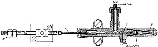
The Stanley power steam cylinder oil pump
on a condensing Stanley operates identical to the power water and fuel
pumps. As the piston is drawn out of the cylinder a vacuum is created
which draws steam cylinder oil from the supply tank to fill the volume
within the cylinder that the piston occupied. The oil is drawn from
the oil supply line and the steam cylinder oil tank into the pump through
the suction check valve while the delivery check valve keeps oil from being
drawn in from the delivery piping.
As the piston is pushed back into the
cylinder the steam cylinder oil that has been drawn in now tries to run back out of the
cylinder through the suction check valve that was open. This action
forces the suction check valve to close and pressure begins to build on the
oil in the cylinder as the piston continues its motion into the cylinder.
When the pressure within the cylinder becomes greater than the oil
pressure of the delivery piping after the pump, the delivery check valve
opens allowing the oil just drawn into the pump's cylinder to escape and
flow into the delivery piping. Once the piston is fully inserted in
the cylinder no more steam cylinder oil is supplied by the pump to the delivery piping
and the cycle starts over with the piston being pulled out of the cylinder
to draw in more steam cylinder oil.
The power steam oil pump in a Stanley is located below or at least at the same level as the
steam cylinder oil supply
tank. This affords an easy way for them to be initially primed with
oil. Rings of graphite impregnated packing are used at the end of
the cylinder to for a seal between the cylinder and moving piston.
Maintenance is generally required every couple hundred miles to snug up on
the packing nut.
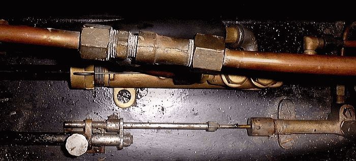
Adjustment of the amount of oil delivered
by the steam cylinder oil pump on a condensing car is regulated by an
adjusting clamp (shown in the drawing above right). A short drive rod
is attached to the power pump crosshead and rides in a guide attached to the
floor of the pump box. This drive rod has a metal tab on the end that
slides along the steam cylinder oil pump's piston rod. The steam
cylinder oil pump's piston rod is extended in length so that it is also
supported by the guide. The pump's piston rod has a fixed stop near
the pump and an adjustable bushing on the piston rod at the opposite end.
The drive rod's tab slides between the fixed stop and the adjustable bushing
as it makes its 4" stroke. By positioning the adjustable bushing
relative to the fixed stop the amount of steam cylinder oil delivered by the
pump can be determined. Generally the pump is adjusted such that as
the crosshead cycles through its 4" travel the steam cylinder oil pump's
piston only moves 1/4" to 3/8". |