|
 The pumps used on Stanley
steam cars manufactured through 1914 are referred to as "short stroke
pumps". A 9/16" diameter piston was used up through 1907 with a
5/8" diameter piston being used on the short stroke pumps from 1908 through
1913 for the 20 horsepower cars. These pumps used 7/16" diameter brass
balls for the check valves. Driven from the right-hand crosshead wrist
pin of the engine, a rocker arm arrangement reduced the 5" engine stroke to
the required 1-1/4" stroke of the pump's piston. The pumps used on Stanley
steam cars manufactured through 1914 are referred to as "short stroke
pumps". A 9/16" diameter piston was used up through 1907 with a
5/8" diameter piston being used on the short stroke pumps from 1908 through
1913 for the 20 horsepower cars. These pumps used 7/16" diameter brass
balls for the check valves. Driven from the right-hand crosshead wrist
pin of the engine, a rocker arm arrangement reduced the 5" engine stroke to
the required 1-1/4" stroke of the pump's piston.
In 1915 Stanley introduced the "long
stroke pump" which ran at a much slower speed and was therefore a lot
quieter than the short stroke pump. Long stroke pumps have a 4" stroke
and use a 5/8" diameter piston. The check valve balls were increased
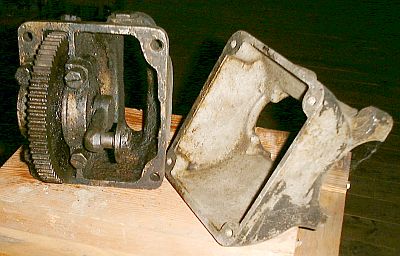
to 1/2" diameter. Mounted on the right rear axle is the pump drive
box. The pump drive box provides gearing and a crank arm to drive the
power pumps. At the end of the crank arm the pump drive rod is
attached. The result is that the pumps operate at a much slower speed
as a result of this design making them quieter (see photo and discussion at
the end of this article on the pump drive box).
Each Stanley power water pump operates
like most standard piston pumps. As the piston is drawn out of the
cylinder a vacuum is created which draws water from the supply tank to fill
the volume within the cylinder that the piston occupied. The water is
drawn in the water supply line to the pump through the suction check valve
while the delivery check valve keeps water from being drawn in from the
delivery piping.
As the piston is pushed back into the
cylinder the water that has been drawn in now tries to run back out of the
cylinder through the suction check valve that was open. This action
forces the suction check valve to close and pressure begins to build on the
water in the cylinder as the piston continues its motion into the cylinder.
When the pressure within the cylinder becomes greater than the water
pressure of the delivery piping after the pump, the delivery check valve
opens allowing the water just drawn into the pump's cylinder to escape and
flow into the delivery piping. Once the piston is fully inserted in
the cylinder no more water is supplied by the pump to the delivery piping
and the cycle starts over with the piston being pulled out of the cylinder
to draw in more water.
The power water pumps in a Stanley are
generally located below or at least at the same level as the water supply
tank. This affords an easy way for them to be initially primed with
water. Rings of graphite impregnated packing are used at the end of
the cylinder to for a seal between the cylinder and moving piston.
Maintenance is generally required every couple hundred miles to snug up on
the packing nut.
Water from the power water pumps is
routed to a check valve just in front of the firewall on the right side of
the car. This check valve is shown on the color diagram and serves to
insure that hot water doesn't flow back into the pumps if the boiler check
leaks or if the water in the feed water heater begins to turn to steam.
From this check valve the water has two paths it may flow. If the
boiler has sufficient water that the feed water automatic is not calling for
water to be added to the boiler, then water from the pumps is routed through
the feed water automatic's water valve and back to the supply tank. If the boiler
needs water added, the feed water automatic's water valve closes off the path to the
supply tank. This causes the water discharged from the two water pumps
to be routed to the feed water heater and then onto the boiler through the
boiler check valve. As there is steam pressure on one side of the
boiler check valve, the check valve remains closed until the pressure in the
piping between the power water pumps and the boiler check valve becomes
greater than the steam pressure in the boiler. The boiler check valve
opens to allow the water from the power water pumps to enter the boiler.
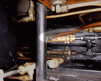
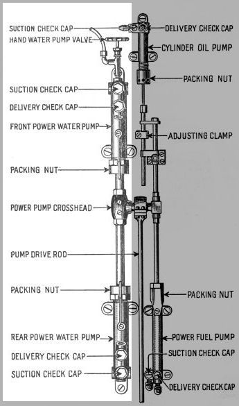
It will be noted in the power pump
diagram above and in the right hand photo above there is a valve attached to
the front power pump. This valve controls water flow to and from the
hand water pump. Generally the hand water pump is not needed and thus
the water supply to it is closed off. This reduces the amount of
effort needed to operate the pump handle as the hand water pump is pumping
air and not water. If use of the hand water pump is required the valve
is opened. Opening the hand water pump valve allows water to flow to
the hand water pump and water can be manually pumped into the boiler.
The plumbing location of the hand water pump valve is between the suction
and delivery check valves thus eliminating the need for check valves in the
hand water pump. Operation of the hand water pump relies on the
operation of the front power pump's check valves to pump water.
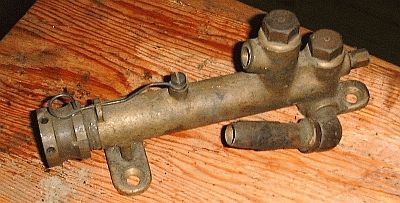
Pictured to the left is a close up of a rear power
water pump from a condensing car. Missing in the photograph is the
pump's plunger or piston which would move in and out at the left end of the
pump's cylindrical brass casting pictured. The lower and right-most
hex-nut on the top of the pump casting provides access to the suction check
valve ball. The suction connection to the pump is attached to the
lower rear part of the pump housing and points upward at a slight angle.
The upper and left-most hex-nut on the top of the pump casting provides
access to the discharge check valve ball. The threaded port for the
discharge of water can be see above the cylindrical pump housing to the left
of the discharge check valve. At the far left is the packing nut that
allows pressure to be applied to the packing rings so that the pump does not
leak as the piston moved in and out of the pump housing. A spring
engages slots in the packing nut preventing the nut from loosening as the
pump operates. To the far right of the pump at the center of the
cylindrical pump casting is a plug. The power pumps are designed such
that they can serve as either the front or rear pump and the plug in the end
of the pump casting is where the hand pump valve would be placed if this
pump were configured to serve as the front pump.
The power water pumps will not pump water if the water
supplied to the pumps becomes too hot. The operation of the pump requires
that the pump’s piston be drawn out of the pump’s cylinder or casting. This
creates a vacuum in the cylinder that is normally filled by water drawn into
the pump. However, if the supply water is close to boiling temperature it
will flash into a vapor (from the air entrapped in the water) due to the
drop in pressure created within the cylinder. Once flashed to vapor an air
pocket forms in the cylinder. As air is many times more compressible than
water, the air expands and compresses to the motion of the pump’s piston and
full slugs of water are not drawn into the pump’s cylinder. If the air
pocket becomes too large the pump can become vapor locked and stop pumping
water altogether.
There are a couple of factors that
contribute to vapor lock of the water pumps. Supply water being close to the
boiling point is the prime cause since it takes water close to the boiling
point for vaporization to occur. For the non-condensing cars the piston
motion is much quicker than that of the condensing-era cars (condensing car
pumps operate at approximately one-quarter the speed of a non-condensing
car’s pumps). The quicker piston motion of the non-condenser car pumps can
aggravate the situation making non-condenser pumps more prone to the problem
than condensing car pumps. Thus the speed at which the car is operated
directly affects the potential for pump vapor locking to occur. Sometimes
slowing down will allow the pumps operate slower and not vapor lock as
quickly.
In addition to hot supply water
causing vapor lock, if the pumps have difficulty in drawing in water, vapor
lock can occur. Looking for any suction line obstructions such as a
partially collapsed hose from the tank to the pumps or a clogged screen on
the inlet to the pumps in the bottom of the water tank will cause the pumps
to have a harder time sucking in water and thus increase the potential for
vapor lock. Water pump supply lines need to be properly sized and kept clear
of sharp bends, restrictions, and obstructions to prevent pump vapor lock
from occurring. If a pump’s inlet check valve is removed with the water
supply tank full of water, a generous flow of water should occur when the
check valve cap is removed.
In some models the steam siphon steam
line is routed in close proximity to the water suction lines to the pumps.
Running the steam siphon allows the heat of the steam line to transfer to
the water line heating the water in the water line to near boiling. When the
pumps try and pump this hot water they vapor lock.
While the condensing cars have slower
operating pumps, the condensing action of the car causes the water in the
water tank to become heated as the car is driven. As non-condensing cars do
not condense the steam back into water and return it to the water tank, the
water tank generally remains at the temperature of the air. For condensing
cars the water leaving the condenser is just below the boiling point of
water. Thus the water returning to the water tank from the condenser serves
to heat the water in the tank. As the car is driven and water is lost from
the water tank due to escaping steam the water in the tank becomes hotter
and hotter. As the water
level gets lower in the tank the potential for pump vapor lock increases.
|