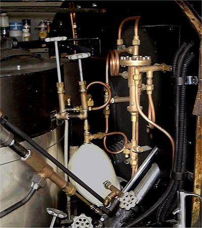
If you review the flow of fuel from the pressure tanks
to the burner you will observe that burner fuel (kerosene) flows first
through the low water automatic, then through the burner firing valve
(located on the dash), and finally to the steam automatic before it can
reach the burner. This arrangement allows for the low water automatic
to insure no burner fuel can get to the burner regardless of the setting of
the burner firing valve. The steam automatic placed last in the fuel
plumbing also insures that if the firing up valve is opened while the boiler
is at pressure, that fuel from the pilot tank will not be fed to the burner
which could cause the steam pressure to rise even though the steam automatic
wasn't calling for the burner to be firing.
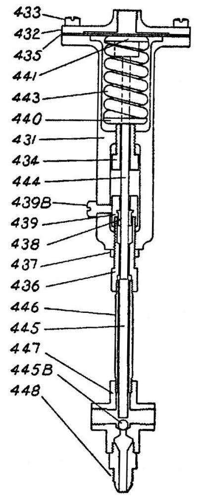
At the top of the steam automatic is a
beryllium-copper disk or diaphragm (435). This diaphragm is clamped between
the two halves of the shell of the steam automatic (431 & 432). The
underside of the disk rests against a washer (441) which helps to keep the
heavy spring (443) centered while steam at boiler pressure is
admitted to the top side of the disk. An adjusting screw (434) and
washer (440) allows for the spring tension against the disk to be set such that the diaphragm
doesn't start moving and compressing the spring until the steam pressure
reaches 500 pounds.
Also connected to the washer (441) at the top of
the spring is a push rod (444) which transfers the position of the diaphragm
to the valve stem (445). At the lower end of the push rod is a packing
gland (438) and packing nut (439) which keeps the kerosene that surrounds
the lower part of the valve assembly from leaking out as the valve operates.
The valve body (447) contains the valve seat (448)
and valve ball (445B) along with the valve stem (445). Kerosene
(gasoline for the early model Stanleys that used gasoline for both the pilot
and burner) from the main burner pressure tanks is admitted through the
valve seat (448) portion of the valve and when the valve is open passes out
through one of two ports in the valve body (447)
When the steam pressure
reaches 500 pounds the diaphragm (435) overcomes the spring force against it and
it moves slightly to compress the spring (443). As this motion happens a
valve push rod (444) moves to apply pressure to the valve stem(445). At the end of the valve stem
the small ball
bearing which acts as the valve (445B) is pressed against the valve seat
(448) by the valve stem.
This action cuts off the supply of fuel flowing though the valve seat (448)
portion of the steam automatic. As long as the ball bearing is pressed into the valve seat fuel flow is stopped.
When the steam pressure drops the spring force
overcomes the steam pressure acting on the disk and the diaphragm moves such
that the valve stem releases the pressure on the ball bearing and thus fuel
can pass though the valve on its way from the main burner pressure tanks to
the main burner. The Cruban
Machine & Tool Works
manufactured various steam car aftermarket parts and even a custom steam
car. Click on the link below to review an advertising card describing
the features of the Cruban Empire Steam Automatic.
~ Cruban Empire Steam Automatic ~ |