BOILER WATER LEVEL INDICATOR ~ KIDNEY DESIGN
   

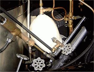
the kidney water level indicator's cast housing is mounted to the boiler side of the firewall and contains a counterbalanced float assembly

located on the dash at floorboard level and just behind the brake pedal the boiler water level indicator displays the amount of water in the boiler

Stanley Motor Carriage boilers generate higher steam pressures (nominally 500 PSIG) than steam traction engine or locomotive boilers (100 PSIG to 200 PSIG). To display the boiler water level in traction engine and locomotive boilers a "water glass" is used. A water glass consists of a heavy-walled glass tube enclosed in a rugged housing such that the glass tube is connected between the bottom (below the water level) and top (in the steam area of the boiler) of a traction engine or locomotive boiler. The water level in the boiler and water level in the water glass seek the same level and thus the amount or level of water in the boiler may be displayed.

However, the pressures present in Stanley boilers negate the use of such devices due to shattering of the glass indicating tube. As a result the Stanley twins invented a device that generally became known as the "three-tube indicator". This ingenious and novel device functions much like a standard boiler water indicator or "water bottle" as they were nicknamed but the glass indicating tube is subject to atmospheric pressure and not the actual boiler pressure as is the case with conventional traction engine or locomotive water glasses. The downside of the three-tube indicator is that unless well maintained it can malfunction and provide a false reading.

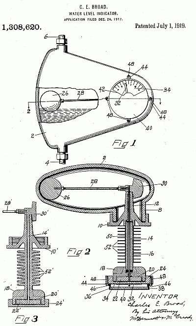
Beginning with the introduction of the Model 735 Stanley the three-tube indicator was replaced with the "kidney water indicator". This device incorporated a heavy cast housing that could withstand the boiler pressures present. Inside the housing was a counterbalanced solid metal float that rotated a magnet. The pointer of the indicator was magnetically coupled to the position of the magnet and thus no seals were present that could leak.  A long neck with cooling fins was provided to radiate the heat away from a shaft that connected the float mechanism inside the kidney-shaped float enclosure with the magnetic indicator.  The device the Stanley's used received Patent Number 1, 308,602, was patented by George E. Broad and was assigned to the Stanley Motor Carriage Company.


patent 1,308,620 ~ water level indicator

Broad's water level indicator design incorporated several unique ideas and these ideas became the basis of the patent.  The first was the use of a solid metal ball (26 in the patent drawing) for the float instead of a solid buoyant material such as cork.  Many float indicators of the period used materials such as cork or wood as the float material.  These materials, while solid, would absorb water over time causing them to sit lower beneath the surface and cause a gradual error in the level to be displayed.  The use of hollow floats also proved unreliable as they were prone to leaking.  The solid float Broad designed was made from a light-weight metal such as aluminum.  The aluminum resisted corrosion and due to its smoothness would not become heavy from the collection of debris, scale, and steam cylinder oil.  Broad then added a counterbalance (30 in the patent drawing) to float arm.  The use of a counterbalance allowed the float to maintain the same buoyancy over time and just lightly float on the surface of the water in the chamber (2 in the patent drawing).

The position of the float was transmitted through a shaft (14 in the patent drawing) which had a magnet (22 in the patent drawing) attached at the other end.  The magnet was located behind a brass cap (24 in the patent drawing) such that the magnetic field would pass through the brass cap.  An indicating needle (32 in the patent drawing) on it's own pivot bearing on the outside of the cap follows the position of the magnet by being magnetically coupled with the magnet.  The brass cap forms part of the pressure vessel subjected to the pressure of the boiler.  However, since the passage alongside the shaft was narrow the force on the brass cap is greatly reduced and thus the brass cap may be made thinner than the walls of the kidney-shaped enclosure the float mechanism was housed in.

Magnetic materials do not maintain their magnetism under high heat conditions and the temperature of the steam and water carried in a Stanley boiler would soon demagnetize the magnet.   Broad's solution was to move the magnet a fair distance from the hot steam and water of the float enclosure (2 in the patent diagram).  He then designed the unit such that condensate surrounded the shaft instead of steam as the water would be cooler than the steam further reducing the possibility of heat getting to the magnet.  The water surrounding the shaft also served to couple the shaft thermally to a cooling jacket that included plenty of cooling fins (52 in the patent drawing) to radiate the heat.

the kidney water level indicator used on stanley cars was invented by charles e broad.  the patent was assigned to the stanley motor carriage company of newton, massachusetts which  was incorporated in delaware.  there were several designs used but all were nearly identical in appearance to the description given in the patent.  shown above are the drawings that accompanied the patent.

© 2003-2012 www.StanleyMotorCarriage.com