|
As Stanley originally intended the
check valve at the boiler to be used in an emergency it is designed a little
different than a standard check valve. The bottom of the check valve
is designed to function like a Stanley's hand valve. The bottom of the
check valve includes a threaded L-shaped valve stem and a valve nut and
valve stem packing as found on any hand valve on a Stanley. When the
L-shaped valve stem is turned such that it threads into the base of the
check valve (the L-shaped valve stem shown in the diagram is rotated
counter-clockwise) it makes contact with the check ball and raises it off
its seat. Thus water can pass through the check valve into the boiler
but it can also pass back out of the boiler and into the piping supplying
water to the boiler.
With the check ball held off of its
seat by the L-shaped valve stem, the check valve would not function only
permitting water to flow into the boiler. If the piping diagram is
reviewed it becomes obvious that the piping of the feed water heater would
always be a boiler pressure since it is effectively part of the boiler.
While the pumps are supplying water to the boiler the feed water heater
piping is subjected to pressures higher than that of the boiler simply
because the pressure of the water must be higher than that of the steam
pressure of the boiler if water is to be pushed past the (emergency) boiler
check valve and into the boiler. However, there is no need to maintain
the feed water heater piping at boiler pressure and thus by allowing the
(emergency) boiler check valve to function as a check valve boiler pressure
can be relieved on the feed water heater piping to only when the pumps are
supplying water to the boiler.
A problem was also discovered with
the (emergency) boiler check valve if the check ball were held off of its
seat by the L-shaped valve stem. The ball, in not bouncing on and off
the seat would become covered with steam cylinder oil over time as the steam
cylinder oil circulated in the water supply system. This coating would
allow minerals and other deposits in the water not captured by the strainer
in the water supply tank to collect on the oil film. The same action
would occur on the check valve seat. When the (emergency) check valve
was required and the L-shaped valve stem was turned (clockwise) to allow the
check ball to be seated, the buildup of oil and deposits on the check ball
and valve seat would not allow a good seal and the check valve would not
block the flow of steam and water back out of the boiler and into the water
supply piping. By allowing the (emergency) boiler check valve to
function continuously it keeps the check ball and check valve seat free of
oil and deposit accumulation and thus functions properly.
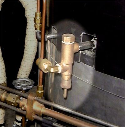
 The
(emergency) boiler check valve is connected to and supported by a pipe that
feeds to the top of the boiler. Examination of the photo at the right
shows the (emergency) boiler check valve connected to the boiler feed pipe.
The top of the boiler is drilled for 1/4" NPT pipe. A 1/4" NPT Tee is
used to make the connection to the top of the boiler as shown in the
photograph. The end of the Tee that is screwed into the boiler has a
special close nipple attached to it. One end of the nipple has a 16"
length of copper or stainless steel tubing welded in place such that the
inside diameter of the nipple and the outside diameter of the tubing are
nearly the same. The tubing is inserted partway into the nipple and
then welded in place. This assembly forms an inverted stand pipe
within the boiler. The
(emergency) boiler check valve is connected to and supported by a pipe that
feeds to the top of the boiler. Examination of the photo at the right
shows the (emergency) boiler check valve connected to the boiler feed pipe.
The top of the boiler is drilled for 1/4" NPT pipe. A 1/4" NPT Tee is
used to make the connection to the top of the boiler as shown in the
photograph. The end of the Tee that is screwed into the boiler has a
special close nipple attached to it. One end of the nipple has a 16"
length of copper or stainless steel tubing welded in place such that the
inside diameter of the nipple and the outside diameter of the tubing are
nearly the same. The tubing is inserted partway into the nipple and
then welded in place. This assembly forms an inverted stand pipe
within the boiler.
The purpose of the stand pipe is to
insure the cooler water being fed into the boiler is fed directly into the
hot water already in the boiler. Thus the cooler water added to the
boiler is being mixed with the hot water already in the boiler. This
prevents a thermal shock from occurring. Had the water being fed to
the boiler been simply plumbed to the top of the boiler and allowed to
cascade into the boiler, it would come in contact with the hot flues and
subject them to thermal stresses which would, over time, cause premature
metal fatigue and failure. By the inverted stand pipe being 16" long
it assures that water entering the boiler is released below the water line
where it can mix with the water already in the boiler (Model 735 boilers
were 18" tall thus the 16" stand pipe would place the water at 2" above the
bottom flue sheet and hopefully 4" or more below the water level in the
boiler).
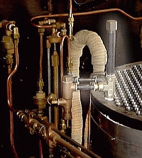
In addition to the connection
between the plumbing tee and the (emergency) check valve there is also a
length of pipe on the remaining port of the plumbing tee. Sitting on
top of the boiler is the smokebox (not shown in the photograph) which
collects up the combustion gasses and directs them to the exhaust duct (see
the discussion on the smokebox). The length of pipe connected to the
top of the plumbing tee is made long enough that it will project up through
the top of the smokebox. This pipe is ended with a pipe cap.
Over time as water is pumped into
the boiler the inverted stand pipe can become choked with buildup and
restrict the flow of fresh water into the boiler. The steam cylinder
oil in conjunction with the dissolved minerals in the water supply will
accumulate on the inside of the inverted stand pipe and reduce its inside
diameter. If not routinely maintained the accumulations will block the
inverted stand pipe and no water will flow to the boiler. The
accumulations effectively become an orifice in the pipe restricting water
flow.
The chocking off of the inverted
stand pipe occurs slowly over time. As a result the power water pumps
are now pumping water through effectively a smaller and smaller pipe.
This causes the water pressures the power water pumps generate to become
higher and higher eventually reaching the rupture point of the copper
tubing. As the buildup occurs slowly over time the driver doesn't
usually notice the pumps starting to "pound" more (this situation is
aggravated as the pumps are in a pump box well below the floorboards and
frame well isolated from the driver by the cushioned car seats and
distance). Since the water flow to the boiler is automatically
performed by the water automatic the driver is also unaware that the pumps
have to function for longer periods of time to compensate for the
restriction occurring (and growing over time) in the inverted stand pipe
(with earlier non-condensing Stanleys the driver had to maintain the proper
boiler water level by operating a valve thus there was some feedback to the
astute driver that the pumps were running more than normal).
The solution is to routinely remove
the cap sticking up through the smokebox on the inverted stand pipe and to
run a wire down the pipe to insure any deposits and buildup on the interior
of the inverted stand pipe are removed. The deposits can become quite
hard and well attached to the inverted stand pipe's interior walls and thus
for extreme buildups a long drill bit may be needed to remove the deposit.
Generally, periodic (once a year nominally) cleanings with a stiff wire
steel brush is all that is needed. The distance from the pipe cap to
the bottom of the boiler needs to be measured and when cleaning is performed
it is important to insure the full length of the pipe is cleaned; nothing
more nor nothing less. The deposits can make one think they are
hitting the bottom of the boiler when inserting the cleaning wires, drills,
and brushes. One also needs to be certain if they are using a very
long drill bit that they actually haven't reached the bottom of the boiler's
flue sheet by mistake and thus end up drilling through the flue sheet
accidentally. |