|
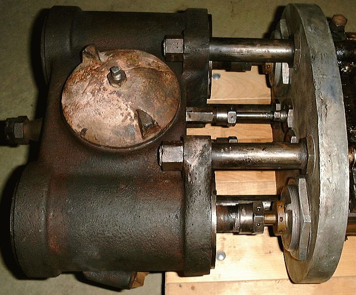
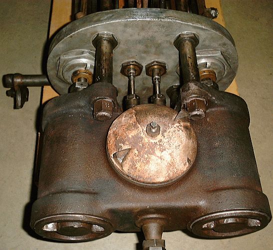
The photograph of the bottom of the engine cylinders shows the domed access cover for the engine's valves. The access cover is spherical so that it is the lowest part of the cylinder area. Any condensate from the steam supply line or from the engine cylinders will gravitate to the dome. A valve, called the drip valve, is located at the bottom of the cover (where a pipe plug is shown in the photograph) and is opened to allow the water to escape. This photograph also provides a good view of the packing glands for the piston and valve rods.
The crankcase baffle includes the valve and piston rod packing glands. The engine support rods are threaded into the cylinder casting and backed up with locking nuts to insure they do not come loose during operation.
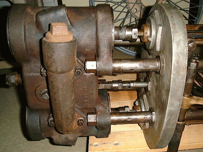
This side view of the cylinder area details the mounting of the exhaust manifold to the cylinders as well as the port (with a pipe plug installed) where the steam supply connects to the engine.
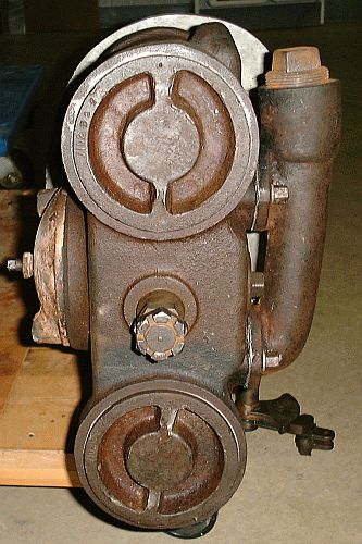
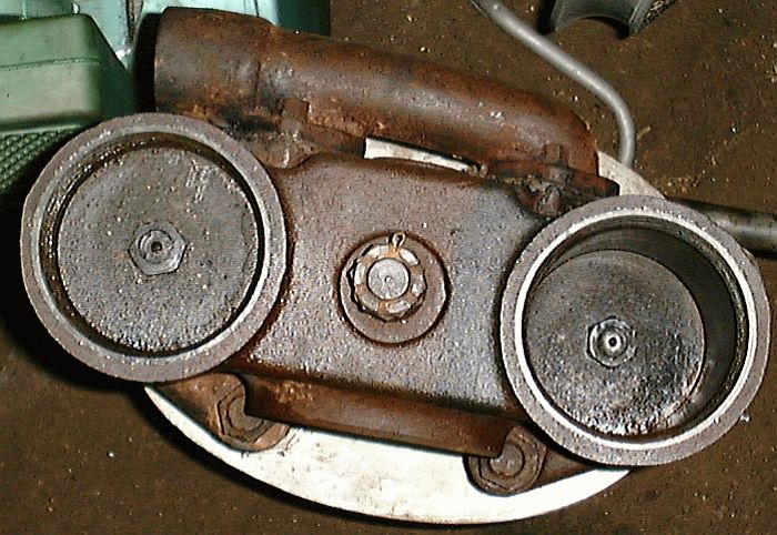
The end of the cylinders showing the cylinder caps. The "bottom" of the engine is to the left in the photo. Both cylinder caps screw into the end of the cylinders and include gasketing to prevent steam leakage. Between the two cylinders is the engine hanger stud that provides support for the engine with a laminated strap to the car's frame. This photo gives a good idea of how thin a Stanley engine is considering the pistons are 4 inches in diameter.
This photo shows the pistons inside the cylinders. The Stanley pistons are about an 1-1/2 inches thick and 4-inches in diameter. The pistons are two identical castings that are screwed onto the piston rod and then a thin nut locks the piston to the shaft. The shaft is then peened to prevent the nut from loosening. Each piston has a pair of piston rings to seal the piston to the cylinder wall and prevent steam from passing from the side of the piston under pressure to the opposite side which is at atmospheric pressure (being exhausted). |
