|
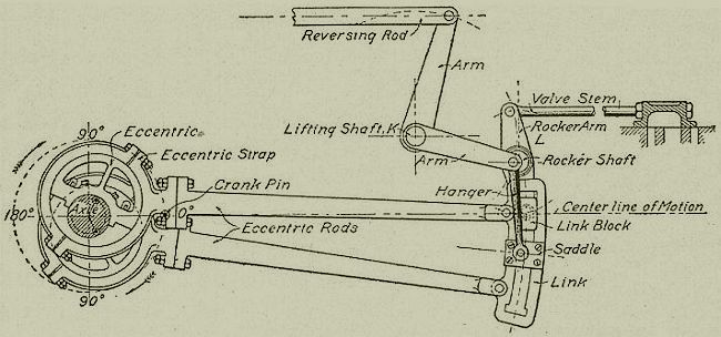
Early stationary steam engines that powered the industrial revolution never needed to "reverse" the engine. The steam engines were set up to drive their loads in one direction only. With the application of the steam engine for marine, locomotive, and eventually steam carriage use, the need for reversing the steam engine became a necessity. Early efforts to reverse a steam engine involved stopping the engine, taking wrenches to the bolts that held eccentrics in place so their position could be changed, and then restarting the engine. The obvious problems were errors in setting the engine's eccentrics for optimum use of steam and power from the engine, the time lost to make the changes, and wear and damage of the engine. The key to being able to reverse a steam engine is in changing when steam is admitted to either side of the piston in the cylinder. A small eccentric attached to the crankshaft moves a valve that controls steam admission to the cylinder at the proper time. Change the position of the eccentric and the motion of the valve is changed with respect to the motion of the crankshaft and thus steam admission is changed resulting in the engine rotating in the opposite direction. William T James of New York invented what became known as "link motion" between 1830 and 1840. His invention applied a pair of eccentrics to the crankshaft that were connected to a curved "link". The link resembled a loop or link of chain and hence its name. By setting a pair of eccentrics at different positions rotationally on a crankshaft and connecting the eccentrics with rods to the ends of the link, the link was made to rock back and forth as the crankshaft turned. The steam cylinder valve (D-slide valve) was then connected to a block that slid in the slot at the center of the link. When the block was slid to one end the engine would run in one direction and when the block (called the Link Block) was moved to the opposite end of the link the engine ran in the opposite or reverse direction.
Initially the position of the link was set with a couple of pins. The engine, when stopped, would have the link pin pulled, the link shifted, and the pin replaced to change the engine's direction. William Howe of Newcastle, England who worked for Robert Stephenson & Company (a locomotive manufacturer), perfected the positioning of the link with the addition of a link saddle to move the link. The link saddle was connected to a series of levers and rods for mechanical advantage and a lever that could be latched in various positions controlled the setting of the link. Howe received permission from Stephenson to try his ideas on one of their locomotives and it proved very successful from the first day it was used. Seeing the potential in the idea Stephenson paid Howe 20 guinea (slightly more than $100) for the idea, adapted the design to his locomotives, and promptly started calling the concept of a shifting link motion "Stephenson Link Motion". Interestingly, neither Stephenson or Howe ever applied for a patent of the idea.
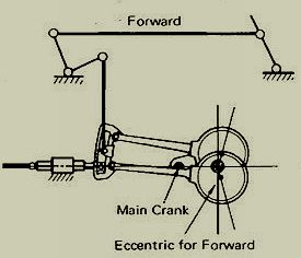
When the link is fully raised as depicted in the
drawing to the left, the eccentric that sets the valve motion for forward
engine operation is directly in line with the valve rod (shown in the
drawing as the line off to the left). Thus as the crankshaft rotates
the forward eccentric directly controls the motion of the valve admitting
steam to either side of the piston in the cylinder. However when the
reversing lever (referred to as the Johnson bar) is moved it causes the link
to "drop" as depicted in the drawing to the It wasn't until later that more experimentation with link motion revealed that intermediate settings of the block in the link would yield improvements to a steam engine's operation and steam use. When set to an intermediate position the engine was termed "hooked up" and the engine's efficiency was greatly improved. Additional forms of valve motion were designed and were more efficient than Howe's link motion. The animation above shows the major link motion valve components for a steam engine of one cylinder. On the right is the crankshaft with the eccentrics. The connecting rod is not shown connected to the crankshaft otherwise much of the eccentric might not be visible. The link is in the "down" position which which causes the crankshaft to turn counter-clockwise. This matches the design of the Stanley engine in that when the link is down the engine's crankshaft turns counter-clockwise and the car moves in reverse (the counter-clockwise rotation of the crankshaft gear meshing to the differential gear causes the differential gear to turn clockwise and the car's wheels to follow). Note how the eccentric rod is in line with the valve rod thus all of the motion of the eccentric is transferred to moving the valve back and forth. As a Stanley engine has two cylinders, two sets of valves are required (one for each cylinder) and thus there are a pair of links and four eccentrics. The speed of a Stanley is controlled with the throttle lever located under the right side of the steering wheel. Only two floor pedals are provided on a Stanley. The right pedal is the foot brake for slowing and stopping the car. The left pedal serves to "hook-up" the engine as well as put the engine in reverse so the car can move backwards. The left pedal, when fully released, allows the engine to move the car forward as the throttle is opened to apply steam to the engine. When the left pedal is fully pressed and held to the floor while the throttle is opened to send steam to the engine, the engine moves the car backwards. Unique to the steam engine is it's ability to run as fast in reverse as it can in the forward direction.
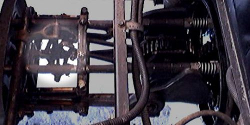
In this video which includes the sounds of the engine operating, the video starts with steam being applied to the engine and it running forward. You'll note in the video that the Stephenson Link is fully raised as indicated in the photograph above. The throttle will then be closed and the engine will come to a stop.
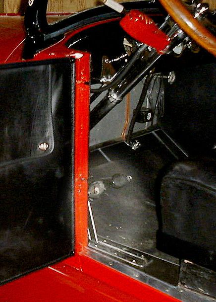
When the engine comes to a rest the hook-up pedal will be pushed to the floor and held pressed to the floor. In the photograph above the foot brake is on the right and the hook-up pedal is on the left. To reverse the engine the hook-up pedal will be held against the floor. You'll notice a small button that protrudes from the surface of the hook-up pedal. This button releases the pedal from hook-up. For additional information on the function of the hook-up button please see the "Hooking Up The Engine" Video.
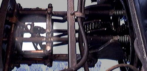
You'll observe in the video the Stephenson Link dropping to the reverse position. The throttle will be opened and when steam reaches the engine it will start running in reverse. After a few seconds of running the throttle will be closed and the engine will again come to a stop.
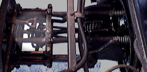
With the engine stopped the hook-up pedal will be released. It will allow the Stephenson Link to rise however you'll note that it will not rise completely. It will stop in the forward "hooked-up" position (shown in the photo above). At this position the steam being admitted to the cylinders is reduced. This position of the link is used only after the car is in motion. Please refer to the hook-up video for a complete description of what hook-up is and how it functions. After a couple of seconds the pedal will be released from hook-up and the Stephenson Link will rise to its full raised position as shown in the initial photograph. Steam will again be applied to the engine and it will operate in the forward direction for a few seconds before the throttle is closed and the engine comes to a rest. In the video the rear axle of the car is supported on a pair of jack stands so that both rear wheels are free to turn. Due to the operation of the differential the left wheel has been chocked to keep it from rotating so that only the right wheel rotates. To view video, click the START button (lower left triangle). The video will start and run to conclusion. The video lasts two minutes and is over 10 megs in size. It will take a few minutes to download.
|
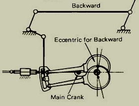 right. With this change the eccentric that sets the valve motion for
reverse engine operation is directly in line with the valve rod (again,
shown in the drawing as the line off to the left). Thus as the
crankshaft rotates the reverse eccentric directly controls the motion of the
valve admitting steam to either side of the piston in the cylinder. By
moving the Johnson bar from one extreme to the other the engine can be
reversed very simply and with little effort.
right. With this change the eccentric that sets the valve motion for
reverse engine operation is directly in line with the valve rod (again,
shown in the drawing as the line off to the left). Thus as the
crankshaft rotates the reverse eccentric directly controls the motion of the
valve admitting steam to either side of the piston in the cylinder. By
moving the Johnson bar from one extreme to the other the engine can be
reversed very simply and with little effort.