|
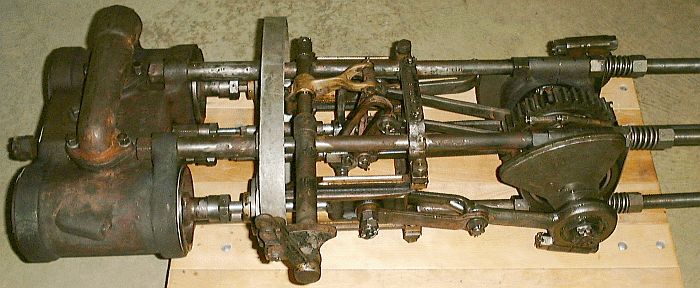
The heart of the Stanley Motor Carriage is its steam engine. The engine was designed to be lightweight but powerful. While the car's horsepower rating was based on the steam generation capability of the boiler (the engine shown below would have powered a 20-horsepower vehicle), the engine for a 20-horsepower Stanley might develop 125 horsepower if steam pressure could be continuously maintained at 600 PSIG. Built on four steel rods, the majority of the weight is concentrated in the cylinder casting at one end and the crankshaft at the other end. In-between are the crossheads and Stephenson Link valve gear. In the center of the crankshaft, a 40-tooth gear mates with the 60-tooth differential gear in a 1.5:1 ratio. Thus no transmission or clutch was required. The Stanley engine included an aluminum baffle between the cylinders and the crosshead. An oval, copper case, spanned the baffle and differential housing enclosing the crankshaft, crosshead, and all the linkages and rods. Filled with several inches of steam cylinder oil, the oil was splashed about the inside of the cover as the engine ran to keep bearings and slides well lubricated. Lubrication of the pistons as they slide in the cylinders is accomplished by injecting a couple of drops of steam cylinder oil into the steam supply going to the engine.
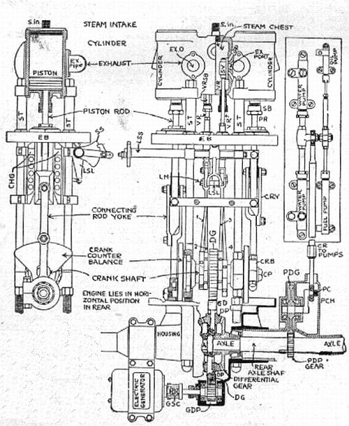
There's only 13 moving parts in a Stanley steam engine as detailed below.
Note: Stanley
only counted major component assemblies. They didn't include The drawing below identifies many of the components of the Stanley Steam Engine.
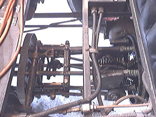
The photograph below is a view looking down on the engine with the floorboards in front of the rear seat removed. The rear of the car is to the right; the front of the car is to the left. By looking at the drawing above and the photograph below many of the engine's components can be identified.
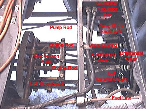
To assist, some of the major engine components have been identified in the photograph below. Normally with the cover removed everything inside the engine would be covered with steam cylinder oil. The videos were made during an engine change before the copper cover was installed and filled with oil. Once the engine cover is in place and the engine run, the oil will be splashed on everything between the front and rear oval baffles by the rotation of the crankshaft counter-balances, crankshaft and differential gears, and eccentrics.
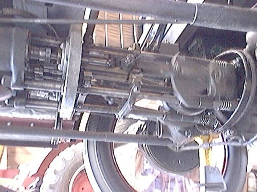
The photograph below, one of the frames of the video, is looking up at the engine from under the left (driver side) running board. As the the frame was taken during the video the crankshaft counterweigh has a slight blur due to its rotation. From identifying engine components in the above photos, the same parts can be identified in the photograph below.
In the video the rear axle of the car is supported on a pair of jack stands so that both rear wheels are free to turn. Due to the operation of the differential the left wheel has been chocked to keep it from rotating so that only the right wheel rotates. To view video, click the START button (lower left triangle). The video will start and run to conclusion. The video lasts one minute and is over 5 megs in size. It will take a few minutes to download. |
|||||||||||||||||