Stanley cars had very simple 6-volt electrical systems. There wasn't a need for an elaborate electrical system since there wasn't an ignition system or starter required. A battery could supply all the power necessary when the car was at rest. A generator connected to the differential gear allowed the battery to be recharged whenever the car was in motion ~ day or night. Thus the Stanley electrical system consisted of a generator, battery, 3 or 4 circuit light switch on the dash, two headlights with high and low beams, a tail light, and a gauge light on the dash. A button next to the driver door sent power to the ahh-oo-ga horn under the hood (steam whistles were never supplied on Stanleys leaving the factory ~ whistles have been added by collectors). An early attempt at electrically heating the pilot vaporizer tube was part of the initial production of 1918 Stanley Model 735 cars but the idea failed miserably and was soon discontinued. The following was the electrical specification provided in Stanley documentation;
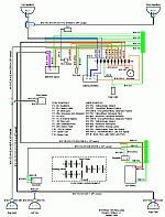
At some period in the car's history a pair of turn indicators (arrow pointing tail lights) were added at the rear of the car along with a self-contained directional switch and blinker on the steering column. Some inexpensive indicators were added to the dash to indicate the operation of the turn signal and the brake light. All of the wiring was cotton insulated stranded copper wire. In restoring the car the fact that only a single fuse protected it all didn't go un-noticed. Add to the equation that much of the wiring was not routed in protective conduits but was instead fastened to the car's wooden body and one starts to wonder about electrical safety. If an electrical fire were to start then having kerosene under 140 PSIG pressure and gasoline under 30 PSIG pressure along with steam oil and horsehair in the leather seats only means the car will be destroyed in no matter of time. Thus the decision to not be totally historically accurate in the car's restoration with respect to the electrical system was made. The electrical system changes included upgrading to a 12-volt system, installing all wiring in flexible conduit of a construction found on other makes of cars of the same era, installation of multiple fuses to protect individual circuits, retaining the existing brake light circuit and turn signal circuits, and remanufacturing all connectors. The first task was to create a new schematic for the car. Click on the "JPG Schematic" link below to see a larger version in a new browser window. Alternatively if you'd like to see the schematic in Adobe Acrobat (PDF format) please click the "PDF Schematic" link below the schematic. |
|||||||||||||||||||||||||||||