|
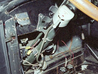
This photo shows the dash wiring. The gray box with lever is the turn signal unit which had been added sometime in the past. The wiring from the unit simply wrapped around the steering column and looped under the dash. To illuminate the boiler water level gauge under the dash a truck marker light, mounted to a piece of strap aluminum, was clamped to the steering column. The wooden dash had been drilled to mount two green (turn signals) and a red (brake) indicator. In addition there was the original Stanley wiring for the headlight, tail light, and dash light that was routed to the 3-button switch unit on the dash and a button on the side wall of the car for the electric horn.
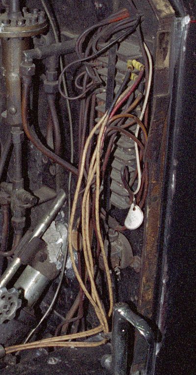
A terminal block was located on the front of the firewall at the left side of the car. The original wiring along with replacement wiring and the wiring needed for the added turn signals and dash lights was all connected to this terminal block. All of the wiring was cotton insulated stranded copper. The original wiring from Stanley had insulation so brittle that it broke off if the wire was flexed. The brighter wire in the photo is replacement wire that had been used to make repairs.
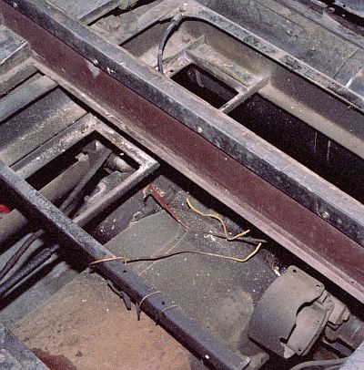
Under the back seat is where the 6-volt battery was located (top center of the photograph). The generator was mounted in the circular steel clamp shown at the bottom right of the photograph. Wiring for the generator had long ago been shorted out and was replaced by whatever was available.
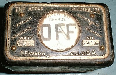
Mounted on the firewall just above the floorboards at the right side of the car was the "automatic switch" for the generator. It's location allowed it to be viewed by the front seat passenger a lot easier than by the driver. When the car was moving fast enough the voltage from the generator closed a contact in the automatic switch to connect the generator and battery together so that the generator could charge the battery. The automatic switch for this Stanley had long been removed and was among a pile of "parts" under the back seat.
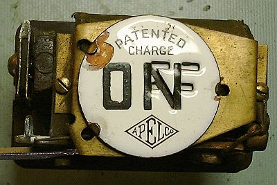
When the generator was connected to the battery the automatic switch indicated ON. A sliding plate behind the front porcelain face of the unit is mechanically attached to the relay's armature such that when the armature moved to close the electrical contacts the plate slide to change the indication from OFF to ON. The electrical contact that closed is located along the left side of the photograph. Switching the current of the generator took it's toll on the contacts such that they literally burned up. You can see the gap between the two contacts (the upper U-shaped contact and its mating knife-edge contact) which is why the unit was no longer in service. |