|
The original Stanley electrical system consisted of an Apple Generator, Apple Regulator, one fuse, a light switch unit with three push-pull switches, and the headlights and tail/brake light. The Stanley Motor Carriage had to have had the most simple electrical system of any car of the time period.
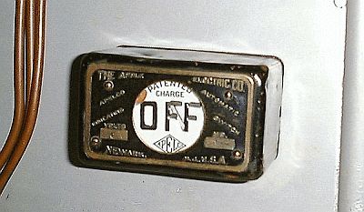
The original generator for the car included a simple ON~OFF regulator for charging the battery. The regulator was mounted at the lower right corner of the firewall just about the passenger floorboards. When the generator was producing a higher voltage than the battery the regulator (shown above) closed a circuit between the generator and the battery and the generator charged the battery. When the generator voltage dropped below that of the battery the regulator disconnected the generator from the battery so that the generator did not start operating as a DC motor and attempt to drive the car (and discharge the battery as a result). The terminal identifications, looking at the rear of the 6-volt regulator, are as follows;
A novel aspect of the regulator was that is displayed whether the generator was charging or not. When the generator was not charging the battery the regulator displayed "CHARGE OFF". When the generator was charging the battery the regulator displayed "CHARGE ON". This was accomplished with a thin flag located behind the main display of the regulator. The main display has the letter O along with the vertical bar of the two Fs painted on the display face. The two horizontal bars of each F were actually cut out of the display so that the flag behind showed the black horizontal bars of the F. When the regulator was active (charging the battery) the flag moved such that the horizontal bars of the F now showed white and a black diagonal bar connected the top of the left F with the bottom of the right F turning them into an N. Thus the display showed "CHARGE ON" You can see the diagonal slit in the face of the display where the diagonal bar of the N will show through when the generator was charging the battery.
The battery is located at the right rear of the car under the rear sofa seat. Access requires removal of the seat and a wooden panel. Originally the battery sat on a pair of angle iron rails and was held in with some sort of a strap. The strap and rods which held the strap in place had been long removed. Modern batteries now come in standard sizes and finding one that fit the space provided by Stanley was not possible. Thus the solution was to add a small metal panel to the bottom of the battery compartment and to supply new threaded rods and clamping strap for the installation. New battery cables complete the battery installation.
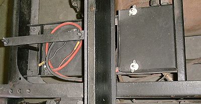
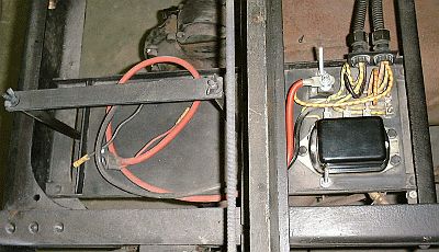
The modern 12-volt generator requires a three-terminal regulator for proper operation. The original dash mounted Apple electric regulator was a simple ON-OFF device that either provided charging or no charging to the battery. Regulation of the amount of current the generator produced was dependent on the speed of the vehicle and how the third-brush regulation system had been set up. A modern regulator provides the ON-OFF control of the original regulator to disconnect the battery and generator when the output of the generator falls to less that the terminal voltage of the battery. Additionally the modern regulator also provides for generator voltage and current output regulation regardless of the vehicle's speed. As the angle supports for the battery were long enough, the metal plate to support the battery was extended the full length of the angles to provide a location for the mounting of the modern Delco-Remy regulator. This arrangement places the regulator under the floorboards of the rear seat just in front of the battery. As indicated in the upper photograph a cover was fabricated to protect the regulator and its wiring. As an aside, if you examine the lower left corner of either photograph you'll observe three "dots" in a row. These "dots" are rivet heads! In 1918 the use of rivets instead of bolts or welding was the state-of-the-art technology for joining structural steel components. The car's frame was pressed from steel channel and angle all held together with rivets. Six carriage-head bolts were used to fasten the car's wooden body frame (covered with aluminum) to the steel channel frame.
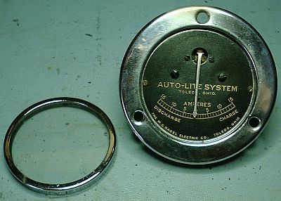
The original generator relay that was mounted to the firewall provided an indication if the generator was charging the battery. The original relay showed ON or OFF depending on what the generator was doing but no indication of how strong or weakly the generator was functioning to charge the battery. At some time in the past, probably when the contacts for the original relay burned up, an ammeter was installed on the car's dash. While definitely not "early 1900s" the ammeter selected was old and thus retained. Pictured above is the ammeter undergoing restoration and current calibration. The ammeter has the benefit that it provided an indication of the amount of charging the battery is receiving as well as the amount of current the battery is discharging. The fact that the meter's maximum scale is only 15 amperes is ideally mated to the generator which now has a derated current capacity due to being totally enclosed and not fan cooled. With all lights on the discharge rate is approximately 10 amperes. |