|
Whether it is and internal combustion engine or a steam engine, there are three fluid systems common to both; water, fuel, and oil. Those fluid systems include a reservoir, piping, and some form of a pump to circulate the fluid in the system. For the Stanley the pumps are of a reciprocating piston design. A Stanley includes a pair of water pumps, a fuel (kerosene) pump, and a steam cylinder oil pump all located in a "pump box" under the passenger seat and right front floorboard. The right rear axle has a gear mounted on it that drives a larger gear that also has a crank arm mounted to it. The crank arm transforms the rotary action of the axle and two gears into a 4" reciprocating action to drive a rod, called the pump drive rod, back and forth. The pump drive rod then attaches to all four pumps.
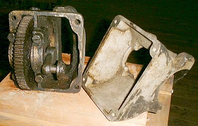
Pictured above is the power pump drive assembly which bolts to the right rear axle. A 31-tooth gear on the right rear axle shaft mates with the 70-tooth gear of the power pump crank gear. The crank arm is designed with a 2-inch distance between the 70-tooth gear shaft and the bearing at the end of the crank arm. This provides for a 4" stroke of the power pump drive rod. With a 40-tooth gear on the engine crankshaft mating with the 60-tooth gear of the differential, combined with the 31-tooth tooth gear on the axle and the 70-tooth gear that drives the pump crank arm, the effective gearing reduces the pump stroke to 3.38 engine RPM to one cycle of the pumps. Due to the differential being part of the gear train this number is an average as differing rear wheel rotation rates will change the engine to pump drive ration slightly.
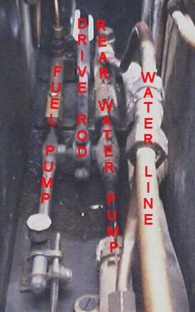
The photograph above identifies the pumps at the rear of the pump box. The four pumps are mounted in an 'H' configuration. The pump drive rod is connected to the cross-bar of the H. At the upper left is the fuel pump while the rear water pump is at the upper right.
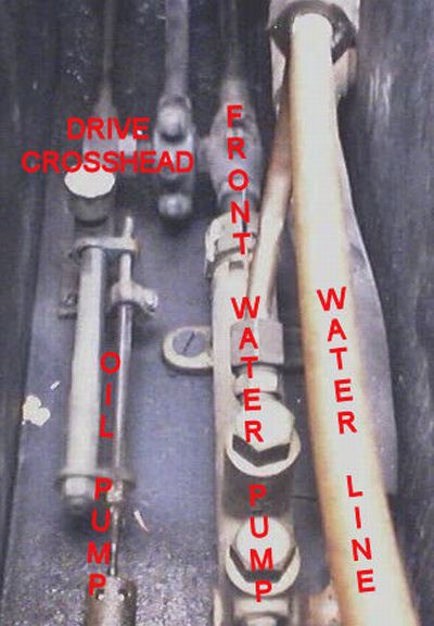
The photograph above identifies the pumps at the front of the pump box. At the lower left is the steam cylinder oil pump while the front water pump is at the upper right.
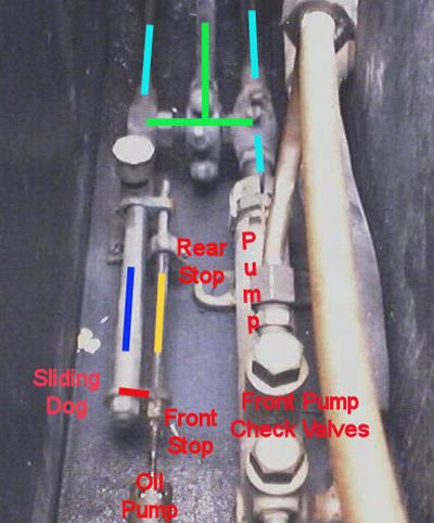
The photograph above identifies various pump drive components. The green lines show the pump drive rod (longest green line) connected to the pump drive crosshead. The light blue lines highlight the water pump drive pistons (right two light blue lines) and the fuel pump drive piston (left light blue line). The various parts of the steam cylinder oil pump have been identified both with text and colored lines. The yellow rod is directly connected to the oil pump's piston. The blue rod is connected to the pump drive crosshead and moves 4" back and forth; the same distance the pump drive moves the pump drive rod and crosshead. The added hardware on the steam cylinder oil pump reduces the travel of the steam cylinder oil pump piston so that the amount of oil delivery can be adjusted. Adjustment of the amount of oil delivered by the steam cylinder oil pump on a condensing car is regulated by an adjustable stop on the steam cylinder oil pump drive rod. A short drive rod is attached to the power pump crosshead and rides in a guide attached to the floor of the pump box. This drive rod has a sliding dog or rod on the end that slides along the steam cylinder oil pump's piston rod. The steam cylinder oil pump's piston rod is extended in length so that it is also supported by the guide. The pump's piston rod has a fixed stop near the pump. The drive rod's tab slides between the fixed stop and the adjustable bushing as it makes its 4" stroke. By positioning the adjustable bushing relative to the fixed stop the amount of steam cylinder oil delivered by the pump can be determined. Generally the pump is adjusted such that as the crosshead cycles through its 4" travel the steam cylinder oil pump's piston only moves 1/4" to 3/8". In the video you'll view the operation of the oil pump and how the mechanism reduces the 4" travel of the pump drive rod to a very short travel for the pump piston. In the video the rear axle of the car is supported on a pair of jack stands so that both rear wheels are free to turn. Due to the operation of the differential the left wheel has been chocked to keep it from rotating so that only the right wheel rotates. To view video, click the START button (lower left triangle). The video will start and run to conclusion. The video lasts one minute, thirty seconds and is over 7-1/2 megs in size. It will take a few minutes to download. The video starts with the engine running slowly while the front section of the pump box is viewed (the 3rd photograph above). After a few minutes the the camera pans up to view the rear of the pump box (2nd photograph above). |