|
Lubrication of the Stanley steam engine is provided by two methods. The crank, piston rods, eccentrics, and crosshead are contained within a copper enclosure with a few inches of steam cylinder oil in the bottom that is splashed about by the action of the crank gear and counterweights as the engine runs. The pistons and slide valves are lubricated as the engine runs by steam cylinder oil injected in the engine’s steam supply. The oil is carried along with the supply steam and lubricates the surfaces of the slide valves as well as the piston and cylinder walls. As the oil-laden exhaust steam is carried from the engine to the condenser the oil is carried along as well. The oil then collects on the cooler inner wall surfaces of the condenser. As the oil collects in small drops it mixes with the condensate. The oil and condensate find their way back to the water supply tank. As the oil is returned to the water tank most of it floats on top of the water in the tank while a residual amount remains suspended in the tank’s water supply. The recycled water containing small amounts of oil is drawn from the tank and passes to the boiler where the oil remains behind as the water evaporates but the oil does not. The oil remaining behind in the boiler collects at the bottom of the boiler in small masses. Proper operation and maintenance of a Stanley includes blowing down the boiler at the end of a day's operation which when done properly generally removed most of the oil and mineral deposits left behind in the boiler from the day's generation of steam. The forming carbon masses absorb oil from the fresh feed water to the boiler which increases the deposit thickness. B eing directly exposed to the heat being applied to the bottom of the boiler the oil blobs carbonize. The carbon deposits form an insulating barrier, slowing thermal conductivity. The thermal resistance of oil is about 1000 times greater than that of steel. A layer of carbon deposits 0.020 inches thick is equivalent to the insulating effects of 0.200 inches of boiler scale.As more oil enters the boiler with water for making steam the deposits thicken and the problem becomes more severe. If the boiler's water content becomes too oil impregnated the water can start to foam (like the head on a glass of beer) due to the increasing surface tension under which the steam bubbles are being formed. The boiler's metal to water heat exchange surfaces become coated with oil and uneven heat transfer and a violent surging of boiler water (called priming) may occur in extreme conditions. The collection of blobs of oil at the bottom of the boiler causes uneven heating of the flue sheet and flue tubes resulting in the flues eventually starting to leak. The Stanley solution was to weld the flues to the bottom flue sheet to make it nearly impossible for leaks to occur. The down side of welded flues is that replacement of the flues becomes more difficult because of the welding and under some circumstances complete boiler replacement is easier than retubing the boiler. Injection of the proper amount of steam cylinder oil into the engine's steam supply when operating can minimize the effects of oil reaching the boiler. However many steam car owners prefer to slightly “over lubricate” their engines to insure minimal wear on sliding valves and pistons. Additionally some Stanley condensing car owners have elected to replace their boilers with less expensive and more readily available non-condensing car boilers (non-condensing car boilers have copper instead of steel flues and the flues are only expanded in the flue sheets instead of being welded to the lower flue sheet as is the case for a condensing car boiler). When this option is exercised the addition of a steam cylinder oil separator is made.
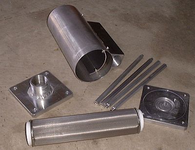
Steam oil separators are metal enclosures of various configurations containing fine wire mesh screens and are often partially filled with stainless steel wool. The object is that the oil mist will collect on the fine wires that make up the screen as well as the stainless steel wool surfaces. As the oil collects it forms into droplets that collect at the bottom of the separator. The collected oil can then be drained off and any oil that is drained off is thus prevented from reaching the water supply tank and eventually the boiler. The ideal separator removes nearly all of the oil while not providing any restriction to the flow of steam through the separator. The operation of separating oil from steam can be accomplished by two methods; coalescing or inertia. A coalescing separator uses a lots of surface area to accumulate droplets of oil through the oil clinging to the separator's maze of internal surfaces. This method relies on the steam passing across many separator surfaces and all the oil making contact with a surface as the oil coalesces from the exhaust steam passing through the separator. Inertial separators are of three general types; impact, cyclonic, and centrifugal. Inertial separators rely on quick changes in direction or the impacting of the oil on solid surfaces to separate the oil from the steam. Even though the replacement boiler was going to be made as Stanley originally designed ~ with steel flues welded to the lower flue sheet ~ a separator was added. The intent of the separator’s design was to capture a large percentage of the exhaust steam cylinder oil. Any oil that would get past the separator and into the water supply tank would be absorbed by oil spill “pigs” that would be floating in the tank.
The steam cylinder oil separator was designed as an aluminum cylinder mounted between two aluminum plates. Clamped between the plates would be a commercially available fine mesh stainless steel cylindrical filter (coalescing separation). Exhaust steam would enter the side of the cylinder where an internal baffle plate would direct it around the circumference of the filter (inertial separation). A layer of stainless steel wool would be placed between the inner surface of the cylinder and the outside surface of the filter to provide additional surface coalescing area for the oil to condense and collect on. Cleaned steam would leave the separator through the core of the filter and out the end of one of the aluminum end plates. A small open space existed at the front right of the boiler compartment just behind the condenser. The separator was designed to fill this space. It was connected to the exhaust steam line connecting the feed water heater and the condenser. The use of unions allows the steam oil separator to be removed from the vehicle, disassembled, and cleaned. A small pipe connection at the center of the bottom end plate provides a means to drain the collected steam oil from the unit. Click here for a section of the Rosedale Products catalog detailing filters ~
Rosedale Stainless Steel Filter Cartridges Click here for my drawing of the steam cylinder oil housing ~
Steam Cylinder Oil Separator Design Click here for the "How It Works" section of this website that discusses the Steam Cylinder Oil Separator ~ StanleyMotorCarriage.com Steam Cylinder Oil Separator How It Works
|